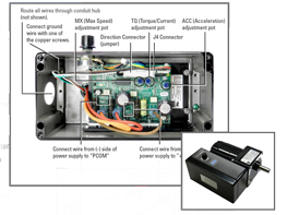
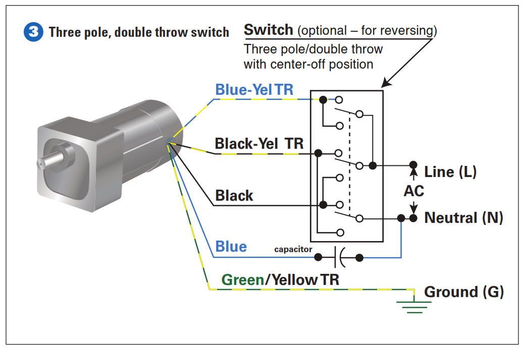
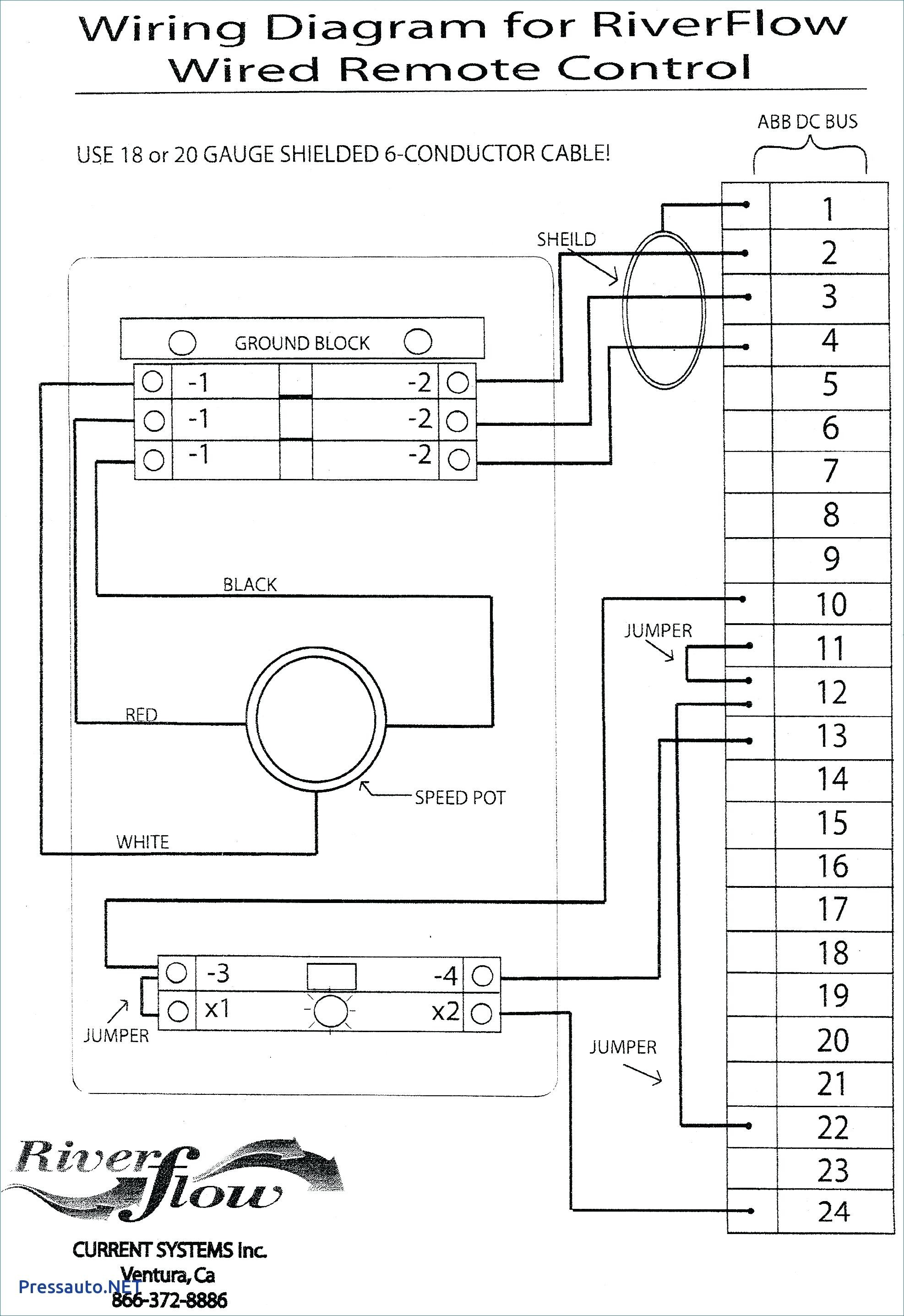
For additional applications and information contact the factory. To verify that this is the correct wiring diagram for your bodine product please check for the connection diagram reference number in the specifications table on the applicable itemmodel page.

Bodine Wiring Diagrams Aero Alpa Leskoyotes Fr
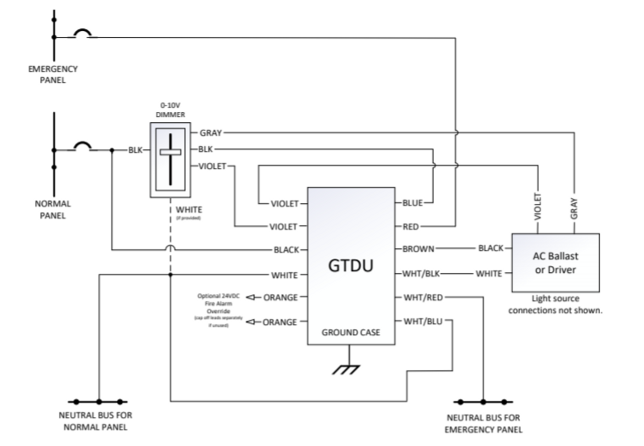
Bodine gtd wiring diagram. Use the proper wiring diagram in the appropriate section of these instructions. A wiring diagram is a streamlined traditional photographic depiction of an electrical circuit. Variety of bodine b90 emergency ballast wiring diagram. Variety of bodine electric motor wiring diagram. For generator or central inverter supplied lighting. Gtd generator transfer device for generator or central inverter supplied lighting.
Buy philips bodine gtd generator transfer device for 9318. Application the gtd emergency lighting control device works in conjunction with an auxiliary generator or a central inverter system to power existing fluorescent or led fixtures for egress lighting regardless of fixture wall switch position. Connection diagram for 230460vac 9 wire reversible 3 phase gearmotors and motors 07410012. An unswitched normal ac power source 120 through 277 vac 5060 hz and a direct separate connection to a. The gtd20a is suitable for use in indoor and damp locations. A wiring diagram is a streamlined standard photographic representation of an electrical circuit.
Philips emergency lighting designs and manufactures award winning innovative philips bodine emergency and specialty lighting products. Philips bodine bodine gtd generator transfer device. Operation the gtd20a senses the loss of normal power and switches the lighting load connecting it to a. The gtd20a includes three dry form c contacts which allows the user a wide variety of wiring options. It reveals the parts of the circuit as streamlined forms as well as the power as well as signal links between the devices. Click download pdf to view this wiring diagram.
In addition to available wiring the device requires a direct unswitched connection to a generator or central inverter supplied emergency panel and an unswitched source on the same branch circuit as the switched supply see diagram below. It shows the components of the circuit as simplified forms and the power and signal links in between the devices.


