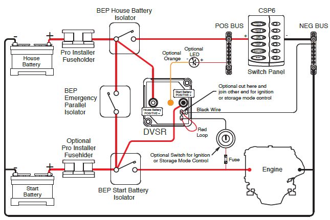
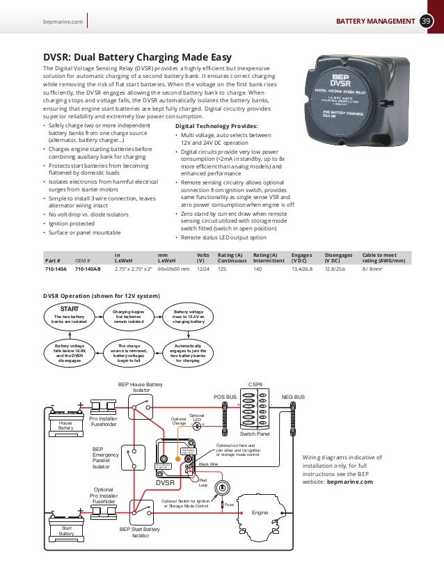
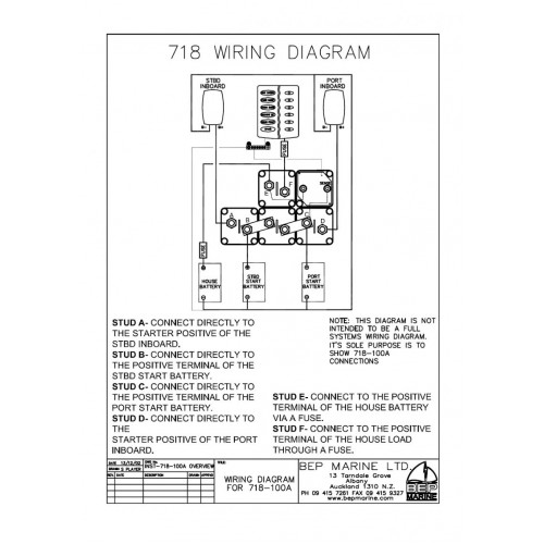
Wiring diagrams dvsr conections house b a t t positive s t a r t b a t t positive house batt positive tinned stud start batt positive tinned stud orangewire remote led indicator output black wire negative red wire ignition controlstorage mode example system. This system is designed for triple outboard installations.
Bep Wiring Diagram Bep Vsr Wiring Question The Hull Truth
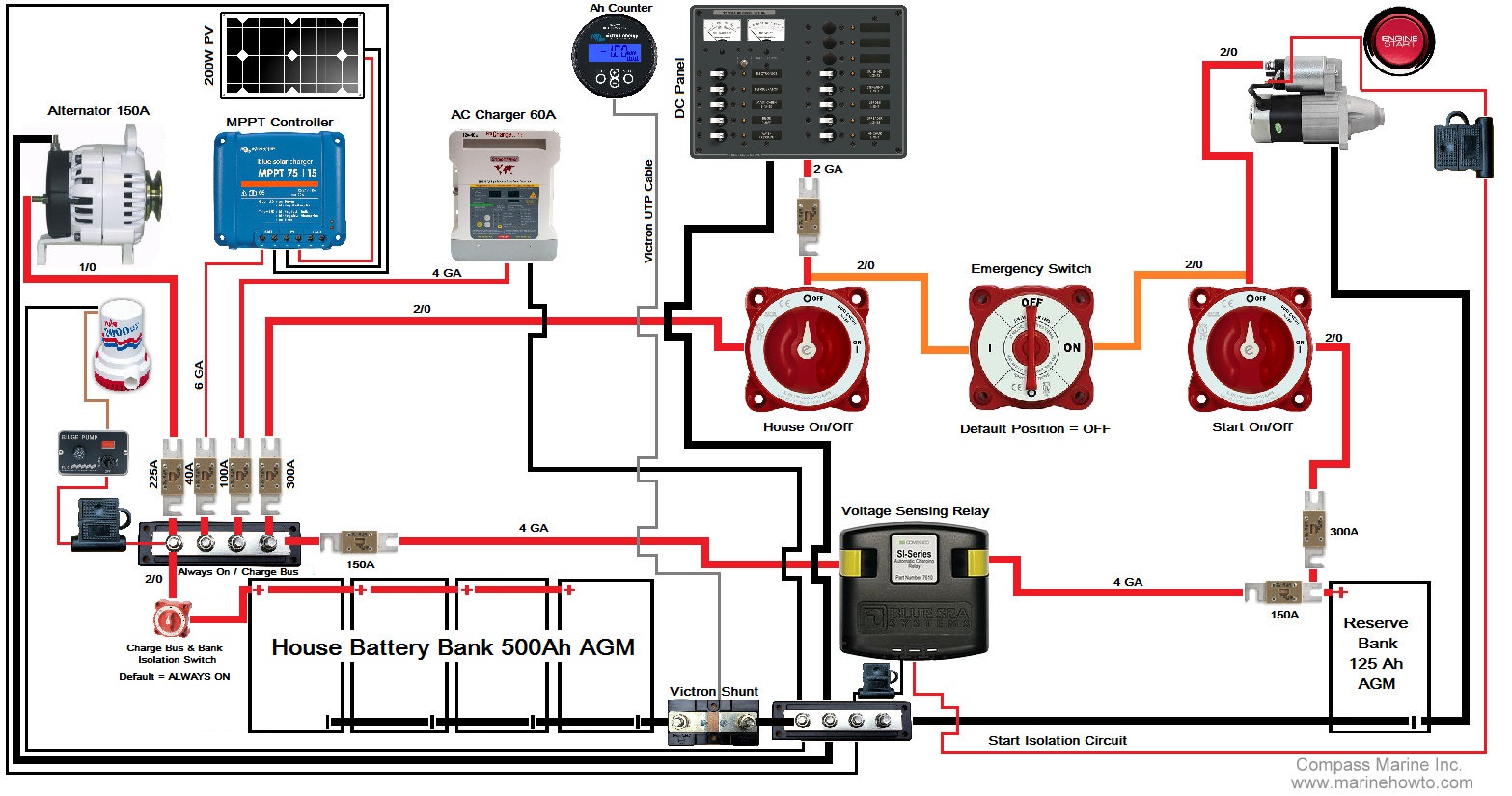
Bep vsr cluster wiring diagram. I am ready to wire in the batteries. Vsr dig 1224v mc compare. I purchased a bep dvsr distribution cluster as recommended on this site. The output wire of the vsr should always be connected to the battery. After reviewing the mercury wiring diagram and the bep wiring diagram i am a bit confused on what to do. Every product it makes meets exacting performance specifications and is designed to withstand extreme conditions both at sea and on land.
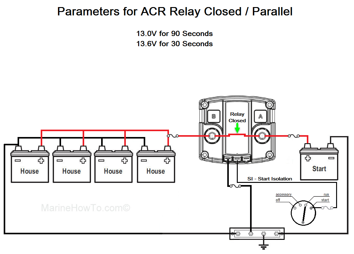
By energizing or de energizing the coil the relay can change positions from open to closed or closed to open. It is vital to follow the wiring installation diagram which shows correct connection to the master switch. Simple to install 3 wire connection leaves alternator wiring intact no volt drop vs diode isolators ignition protected surface or panel mountable replaces previous models 710 125a and 710 125a ds multi voltage auto selects between 12 and 24v dc operation digital circuits provide very low power consumption and enhanced performance. Bep engineers and manufactures a range of high quality electrical solutions designed for the harsh marine and rv environments. In this image we are looking at the guts of a combinervsr that was 7 years old. Bep catalog bep 40 42 apollo drive albany auckland 0632 new zealand 64 9 415 7261.
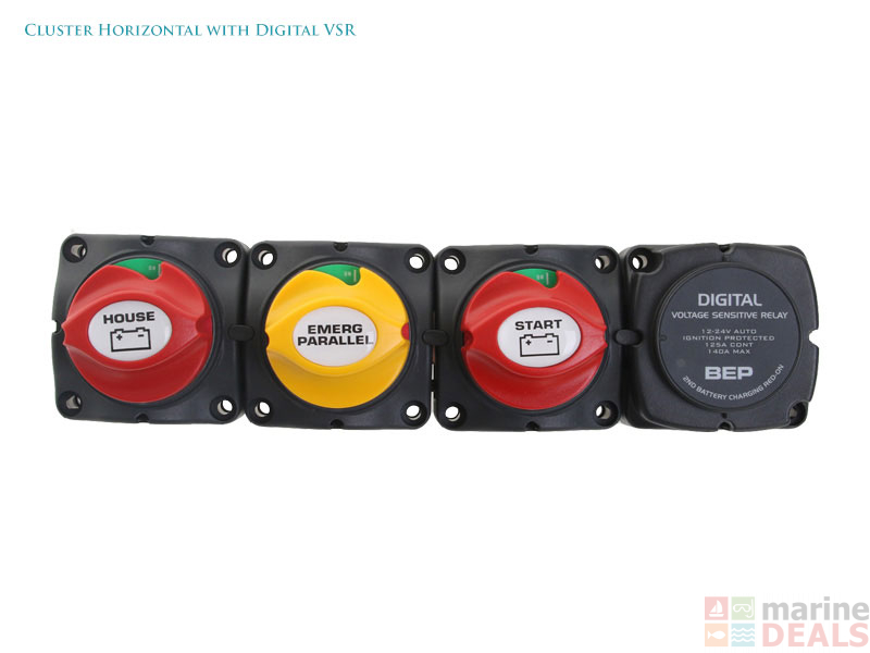
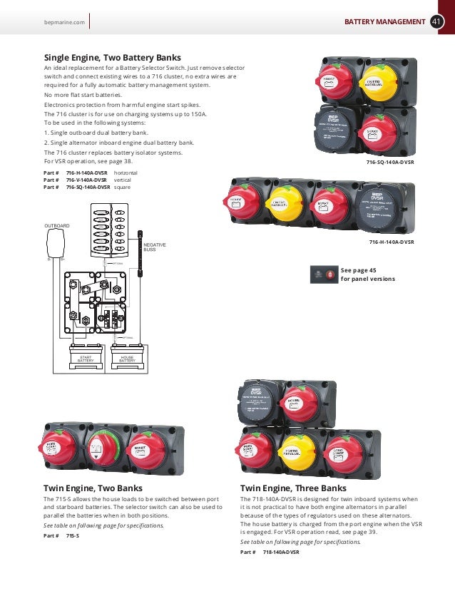
Once again using multiple vsrs off each start battery giving combined charge from all 3 outboards into the house battery via vsrs. The 719 140a dvsr was designed through popular demand for our 717 140a dvsr cluster. Cc single eng bat selector vsr mod compare battery management contour connect panel for twin engine with vsrs part cc 803n cc twin eng bat sw dvsr combo 2x3 mod compare prev 1 next. I am re rigging my entire boat from scratch. New vreado 350s are coming next week. Bep who make vsrs have this suggested wiring diagram which also has a third simple onoff switch to link the house batteries to the cranking batteries for emergency starting this may not be the best way to do this but thats another subject.
Bep only recommends the supplied option. Other options can lead to accelerated battery discharge as the sense circuit draws 00 amps continuously. Note this diagram is a guide only showing. Any idea what would also saw a nice diagram of the wiring but you used both a vsr and an isolator. The onoff switches can be. A relay is the control device used inside a combiner vsr or acr.
It is nothing more than an electronic switch that is closed or opened using a relay coil. Single engine with two battery banks with motorized vsr part clstr bat sw 2xb mdvs sglthe digital voltage sensing relay dvsr allows the charging of a second battery bank from any single charging source. A vsr voltage sensitive relay is a good way to control the charging.


