When there is a power failure on mains 1 the pfr will open. Bbv51330 092015 7 steps for setting up the soft starter also refer to quick start guide 1.

Soft Starter Wiring Diagram Ats01n125ft 7 2 Ats22d47q
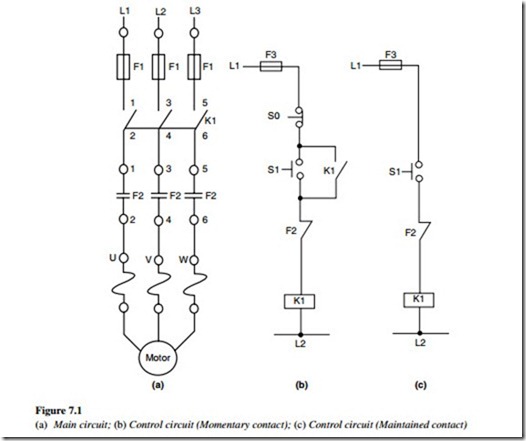
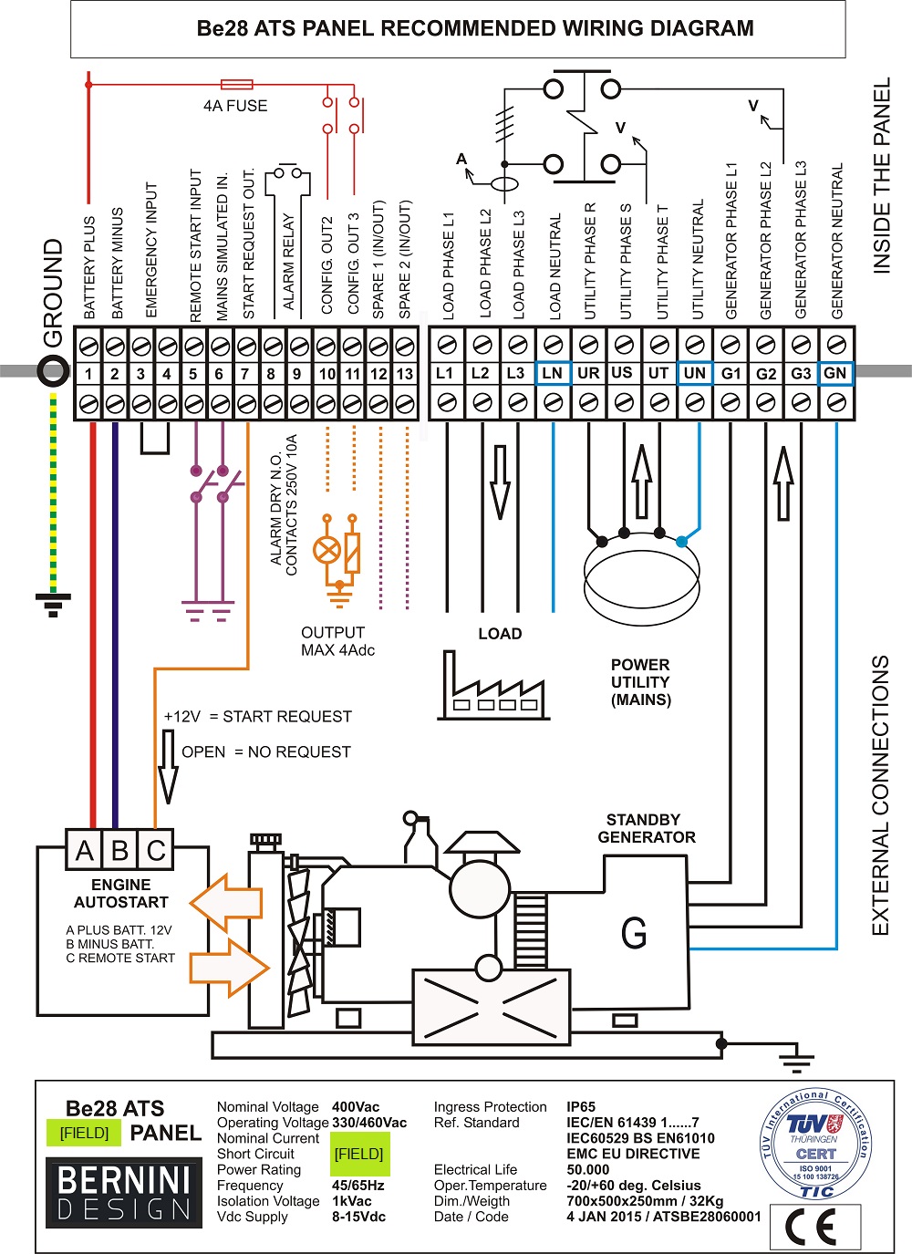
Ats starter control wiring diagram. From l1 the phase current flows to thermal overload contact through fuse then off push button on push button interlocking contact 2 and. Refer to figure 1 and to the wiring diagrams in appendix a beginning on page 79. The upper portion of the changeover switch is directly connected to the main power supply while the lower first and right connections slots are connected to the backup power supply like generator or inverter. Generac 100 amp automatic transfer switch wiring diagram. Whole house transfer switch wiring diagram awesome 11 plus generator. Control 3 phase motor from more than two places power control diagrams.
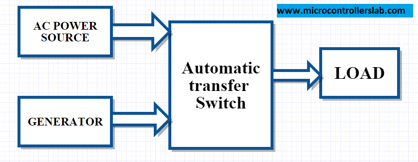
It uses two contactors two auxiliary contact blocks an overload relay a mechanical interlock two normally open start pushbuttons a normally closed stop pushbutton and a power supply with a fuse. A smart way to build an automatic transfer switch is by using two contactors together with an ats controller. Check the line voltage compatibility. Receive and inspect the soft starter v check that the soft starter reference on the nameplate is similar to the purchase order. V remove the altistart 22 from packaging and check that it has not been damaged 2. Full voltage reversing 3 phase motors.
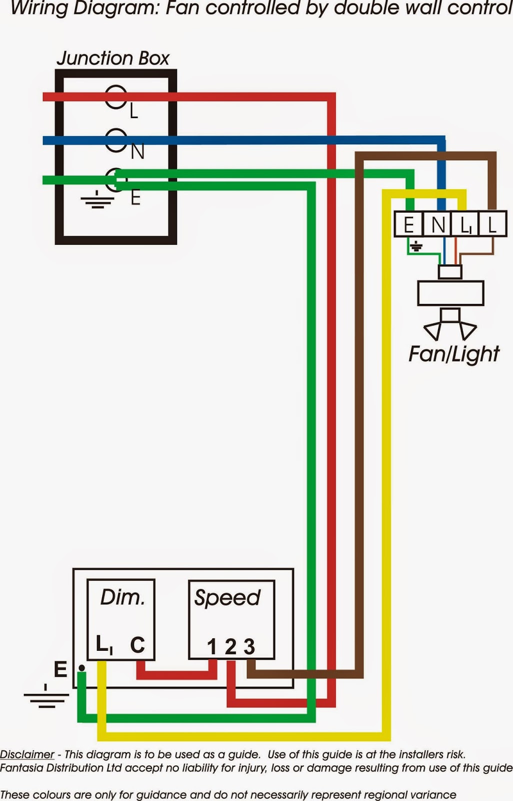
This diagram is for 3 phase reversing motor control with 24 vdc control voltage. Generator automatic transfer switch wiring diagram generac with. Soft starter ready when power and control voltage are present and the motor is not operating nlp when power is not supplied logic inputs li1. A wiring diagram is a streamlined conventional pictorial representation of an electric circuit. Assortment of asco 7000 series ats wiring diagram. The contactors are not allowed to close simultaneously but only one at a time.
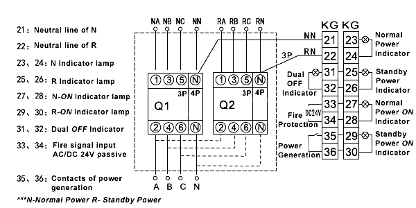
Generac automatic transfer switch wiring diagram for exelent an architectural circuitry representations show the approximate places as well as interconnections of receptacles illumination and also permanent electric solutions in a structure. Power block diagram 1l1 a2 2t1 3l2 b2 4t2 5l3 c2 6t3 ac line supply 2t1 4t2 6t3 motor a2 b2 c2. Operation working of automatic star delta starter. It is about two electrically controlled circuit breakers. The idea of the system is simple. In fig 2 different connection and wiring diagrams are shown for a two pole single phase manual changeover switch.
Interconnecting cable paths might be shown around where specific receptacles or components need to. Generac 200 amp automatic transfer switch wiring diagram sample generac 100 amp automatic transfer switch wiring diagram elegant 16. In this video you will find out how to use phase failure relay in simple auto changeover application. Stardelta starter without timer power control diagrams wiring diagrams. It shows the parts of the circuit as streamlined shapes as well as the power and signal links in between the gadgets.


