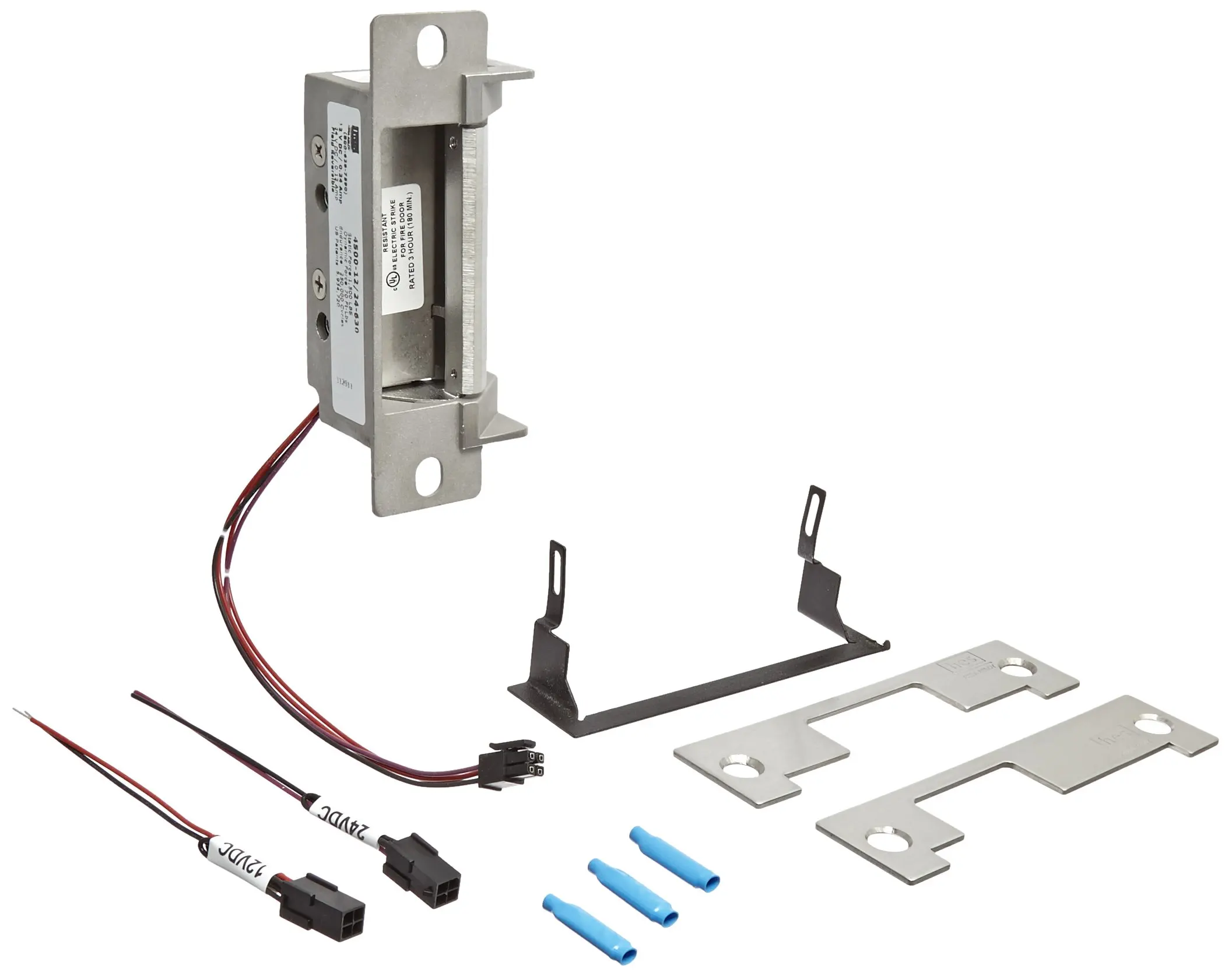
Some examples are shown below. Product components 940095009600 strike body 940095009600 cover 14 20 x 1 mounting screws 10 32 10 24 lockdown screws optional 6 32 x 14 cover screws 564 hex key 12.

Checklist S3 Price Books Sargent Locking Hardware Mp 1
Assa abloy 9400 wiring diagram. Use proper hardware best suited for each particular door installation. It is the respon sibility of the door owner to ensure that the wall material is strong enough to support the forces of the door and all anchoring hardware. The surface mounted windstorm rated solution. No frame cutting required. Narrative in conjunction with a wiring diagram setting up advanced wired systems and product troubleshooting. Faceplates accessories documents certifications listings.
Summary of contents for assa abloy hes 9400 page 1 hes 940095009600 electric strike installation instructions and frame preparation product components diagram 1. The 9400 electric strike is a slim line surface mounted electric strike designed to accommodate rim exit devices with a 12 inch pullman latch. Product components 9400950096009700 strike body 9400950096009700 cover 14 20 x 1 mounting screws 10 32 10 24 lockdown screws optional 6 32 x 14 cover screws 5. Assa abloy booth features hes company electric strikes duration. It uses existing id badges so there are no keys to control or replace and no codes to secure or remember. Hes 9400 series surface mount electric strike installation.
Series electric strikes strike monitor lbsm refer to diagrams 3 and 4 onwiegand wiring. The class includes instructional and hands on exercises covering the following subjects. Assa abloy does not supply hardware for mounting the door to the wall. To learn more see pages 82 and hes series cabinet lock versatile compact and cost effective the hes. Hes 9400 series assa abloy. The 9600 series is a windstorm rated surface mounted electric strike designed to accommodate rim exit devices with a 34 throw latch.
Est monday through friday. Summary of contents for assa abloy hes 9400 page 1 hes 9400950096009700 electric strike installation instructions and frame preparation product components diagram 1. Wiring door stations and power supply duration. Prefer to speak with us. Power supply circuits 20 min load calculator20 mins operational narrative 20 min creating wiring diagram 20 min. Single door controlled egress wiring diagram 01 single door digital entry wiring diagram 10 single door dk 26 with door prop alarm wiring diagram 15 single door dk1 11 xms dt 7 wiring diagram 20 single door dk 26 remote release wiring diagram 14 single door dk 26 unl 24 and dt 7 wiring diagram 18 single door dk 26 using the hard code to toggle lock off and on wiring diagram.
Representatives are available 8 am.


