The main role of an armature is multi purposed. The location of the winding depends upon the type of machine.

Types Of Armature Winding Ac And Dc Armature Winding And
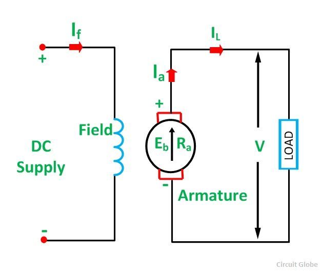
Armature wiring diagram. Plus the wire used is not a wire its actually a cotton string. The designing of the armature winding can be done using the copper. For a more detailed schematic specific to your piece of equipment your best source of. The current in the armature winding is known as the armature current. Copper armature wiring enhances electrical efficiencies due to its higher electrical conductivity. Generally there are two types of armature winding in the dc.
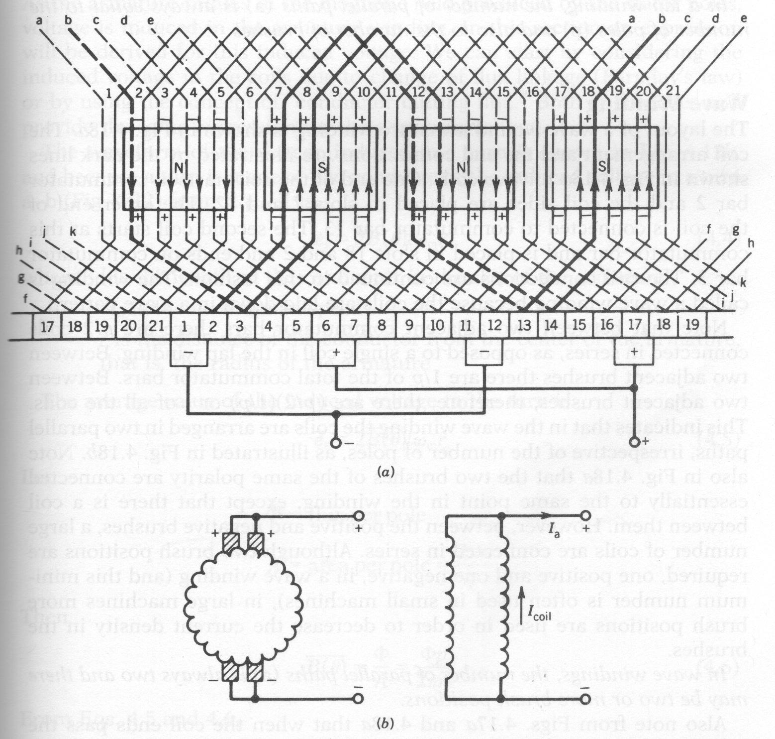
The armature winding is the main current carrying winding in which the electromotive force or counter emf of rotation is induced. Front side and end on. I got the simplified diagram for a black decker drill i hope this can help you in repairing black decker drills. A schematic winding diagram for a dc machine with a commutator showing a wave winding shown as if the surface of the armature was flattened out. The armature takes the place of the nail in an electric motor. Aluminum armature wiring is.
Also i forgot the model of the armature used or what kind of power tool it belong and the commutator and armature are already broken. The primary role is to transmit current across the field therefore generating shaft torque within an active machine otherwise strength in a linear machine. The armature diagram is shown below. In addition to wiring diagrams alternator identification information alternator specifications and procedures for the replacement of an older briggs stratton engine with a newer briggs stratton engine that utilizes a different style alternator output connector are also available in this guide. Before the process of winding starts then the core slots will be protected from the copper. The winding continues to loop all the way around the armature in the same manner.
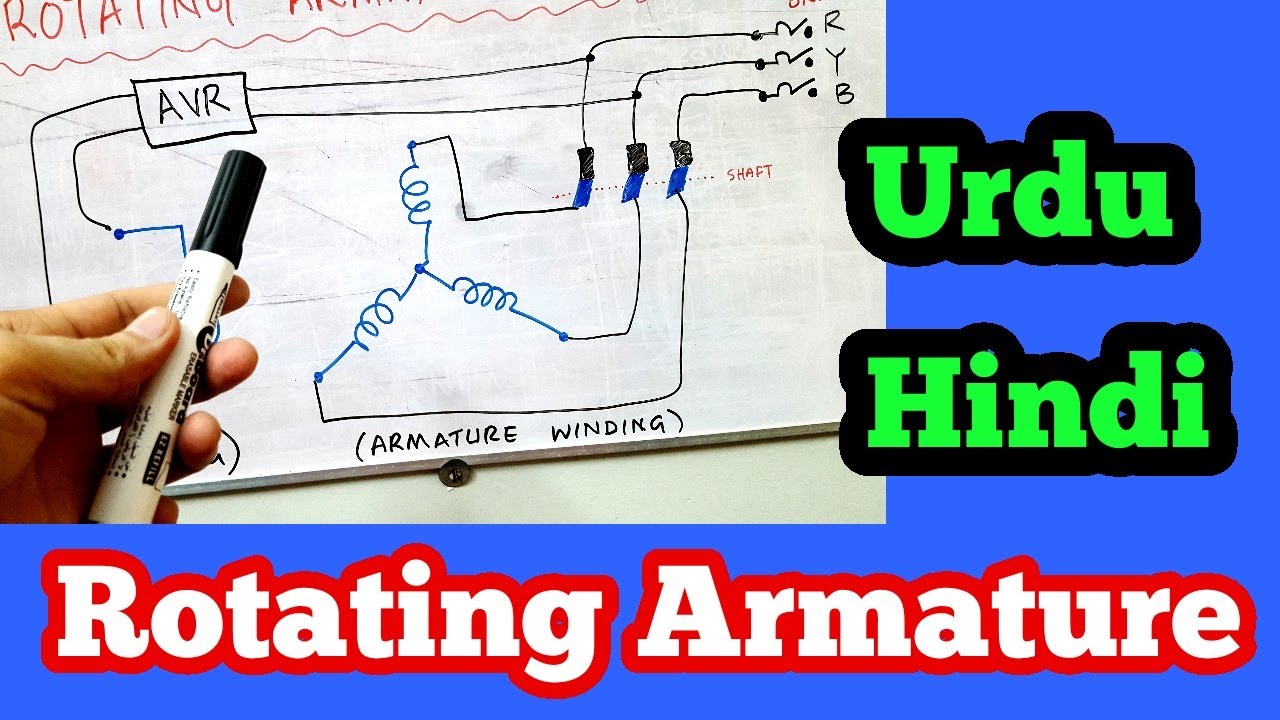
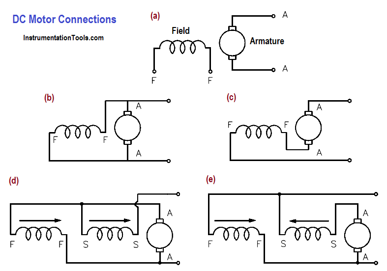
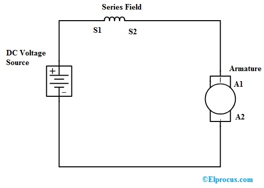
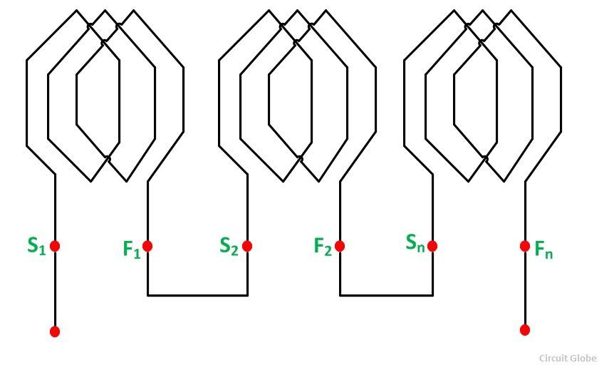
The dc motor armature winding diagram is shown below. Generally this is housed on stator slots and field winding on rotor slots to machine synchronous. Basic armature design an armature pictured on right has a continuous series of windings from each bar on the commutator which loop around the iron stack teeth and connect to the next bar on the commutator. 3ø wiring diagrams 1ø wiring diagrams diagram er9 m 3 1 5 9 3 7 11 low speed high speed u1 v1 w1 w2 u2 v2 tk tk thermal overloads two speed stardelta motor switch m 3 0 10v 20v 415v ac 4 20ma outp uts diagram ic2 m 1 240v ac 0 10v outp ut diagram ic3 m 1 0 10v 4 20ma 240v ac outp uts these diagrams are current at the time of publication. Voltage 220 commutator segments 24 armature slots 12 wire number 29. This winding is placed in the slots of a rotor whereas the field winding is placed in slots of the stator.
The armature has an axle and the commutator is attached to the axle. Armature wiring is made from copper or aluminum. The armature is an electromagnet made by coiling thin wire around two or more poles of a metal core. In the diagram to the right you can see three different views of the same armature.
Gallery of Armature Wiring Diagram