The most common is the rj 11 which uses only 2 of the wires in a 4 or more strand wire. Typicslly the modular connectos used in telephone have.

Bcm 50 Main Unit Wiring
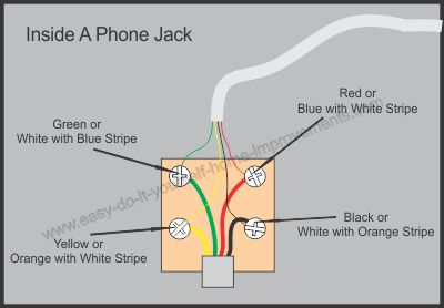
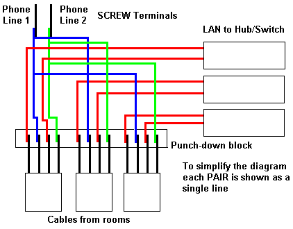
Analog phone wiring diagram. Typical wiring for 6 pin modular connector. Red wire green wire. This telephone wiring diagram with photos and instructions will show you the direct steps to correctly wiring a telephone jack. In normal telephoen wiring used in finland usa and very amny other countries the telephoen audio and sing signals share the same wire pair. Phone jack wiring telephone wiring. How to wire a phone jack voice or telephone rj 11 thru rj 14 usoc wiring diagram telephone wiring for a phone outlet is typically either 1 2 or 3 pairs 2 4 or 6 conductor.
An rj11 cable with 2 conductors 6p2c can only handle a single analog phone line. The typical rj 11 connector has six terminals. The diagram is shown with the hook clip on the underside. There may be instances where you may need to connect to or transpose from the old quad cable. The above diagram shows which pins will connect between an rj11 cable and an rj45 connector. Connecting voip to a legacy pbx system.
In most residential phone wiring the cable contains four individual wires. Standard analog phones the type you generally connect to traditional analog telephone service receive electronic analog signals through two copper wires inside a phone cable. For all new telephone wiring projects you should use cat 5 cable. Most phone wire installed in the us. Most cable nowadays is utp unshielded twisted pair. This wiring diagram shows the standard way to wire telephone jacks the single line set will use the following pairs depending on your cable.
This is the same kind of plug that you use to plug your telephone into the wall. The kind of wire shown above has recently become obsolete. We need to connect our battery and resistor to either the red or the green wire. One end of the cable is connected to a telephone wall jack the other end to a jack into which is connected your dial tone service. During the second half of the 20th century is of the following kind. 1 2 3 a wire 4 b wire 5 6 a and b wires make the pair which telephone used.
There are 2 types of common modular plugs the rj 11 and the rj 14. Inside most phone cords there is a red wire and a green wire. At a wall jack one end of a telephone line cord is plugged into the jack the other end is plugged into the telephone. Telephone wire comes in 2 gauges 22 gauge and 24 gauge 24 gauge being todays standard. Usually only the middle four pins are used. These 2 wire are normally referred to as a wire pair.
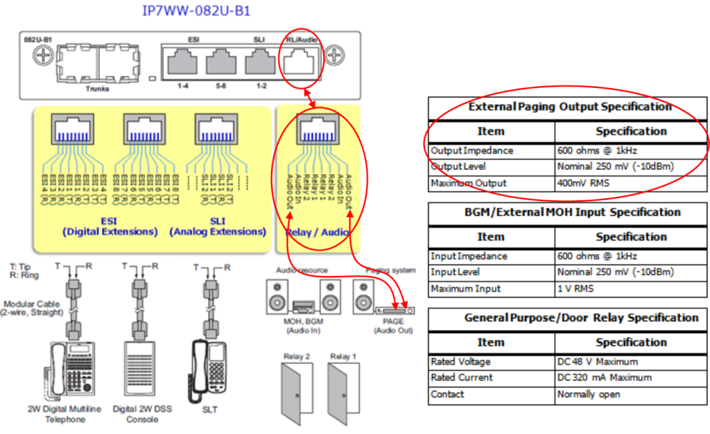
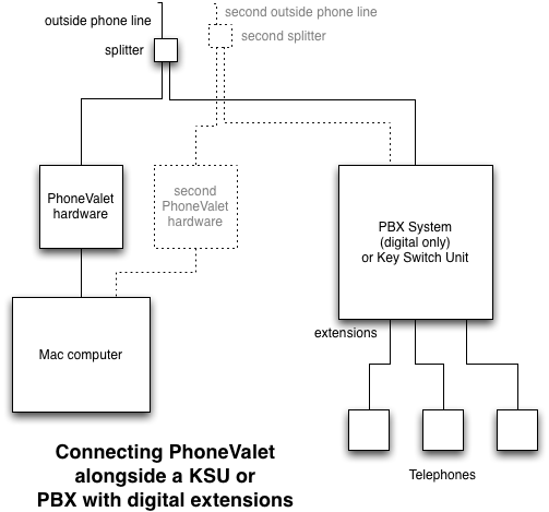
The fxo line port of a voip telephone can be connected up to an analog extension port of a pbx system in just the same way it. This type of cable can handle two different analog phone lines simulations. When an rj11 cable is plugged into a female rj45 connector the center pins will line up. If your cord has four wires red green black and yellow you only need to pay attention to the red and green wires. The pots plain old telephone service residential telephone wiring generally contains two pairs of wires designed for two separate telephone lines.
