In the normally open circuit the 2k end of line resistor connects across the two terminals at the last panic switch wired in the. Can i add panic alarms to each till by simply daisy chaining all the buttons to one another.
How Do I Fix My Security Alarm Top Tips Dengarden
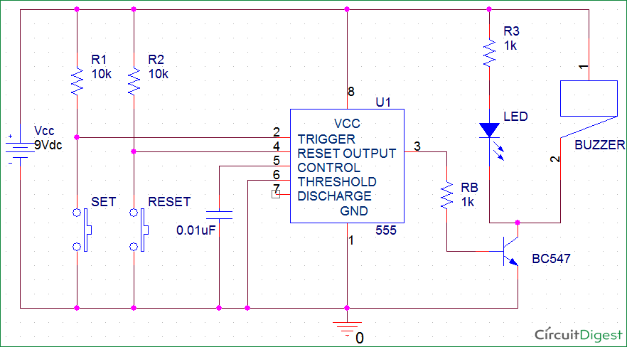
Alarm panic button wiring diagram. Remote push button with electric latch release. 15 apr 2005 messages. When recommending panic buttons to commercial customers alarm installers should offer to tie the panic button to the surveillance system. After analyzing the on and off time period of the panic alarm circuit given above we find that the circuit will remain on for about 0845 seconds and off for about 0152 seconds. This is a simple circuit named panic alarm which helps in intimating others regarding our bad situation without any delay. Eletric panic trim wiring diagram.
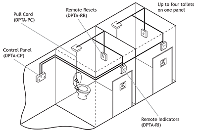
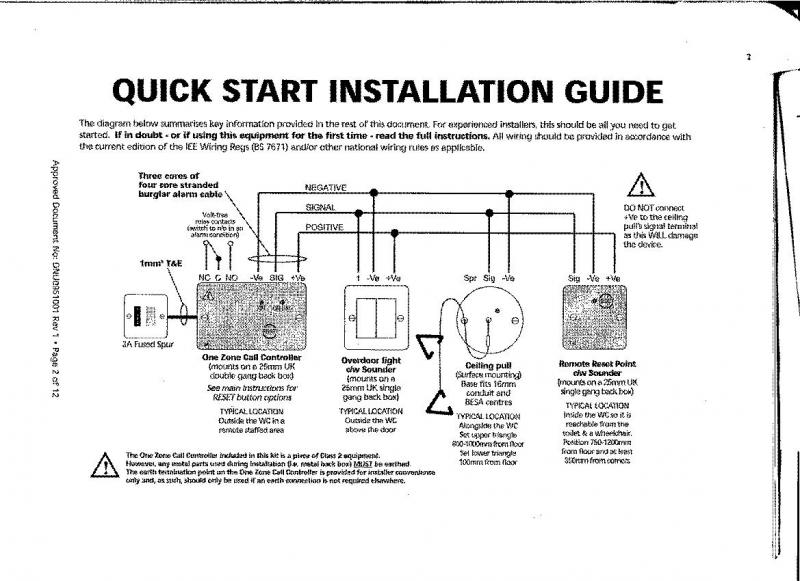
Or does each panic button use its own pair of wire. This is called wiring in series. Controller combined power supply and controller with reset button audible alarm large diameter led. Open normal closed alarm panic button 1 open normal closed alarm panic button 2 when the red button is. This disabled wc alarm kit provides a compliant reliable and easy to use disabled persons toilet alarm which contains the following devices. Home alarm test panic buttons.
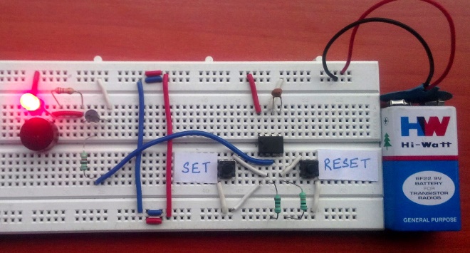
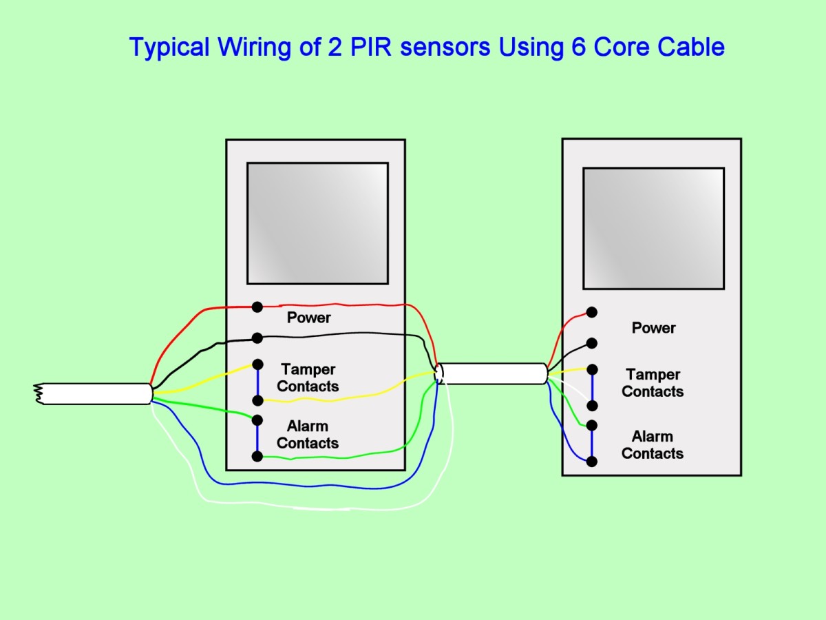
One problem im abit unsure of is wiring up panic alarms for a number of checkouts. It is possible to wire more than one pa button to the one alarm system to do this simply wire the buttons in series as you would do with the tamper circuit. Panic button panic button 1 panic button 2 panic button features switch states the normal state for the panic button is the red button in the up position not pressed. Electric latch retraction with auto operators. Fail safe electrified breakaway lever with push button and fire alarm release fire rated application. Panic alarm circuit diagram.
This circuit would not be monitored but for domestic purposes where the alarm is not monitored this may not be important to you. Thepprentice 23 oct 2007 1. Wiring a hold up button directly into an ip camera or dvr that offers dry contacts allow the recorder to bookmark the activation as an event making it easier for security officers to search for and save. The circuit is in the disabled mode when the button is not pressed and hence the alarm will not function when the button is not pressed. If you havent got the resistors cant get any more or would find it easier not to use them then you could wire in the alarm pair only and fit a short link wire across the tamper terminals in the panel. This circuit is made with a low cost hardware using ic 555 timer buzzer a few resistors and capacitors.
Access control on egress doors. As you can see in the normally closed configuration the 2k end of line resistor connects to one side of the last panic switch in the circuit and only one of the zone terminals. Custom wiring diagrams. As above only two wires needed for fsl wiring method. The alarm state is the red button in the down position pressed. Ceiling pull switch with led.
Gallery of Alarm Panic Button Wiring Diagram