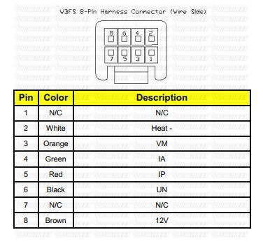
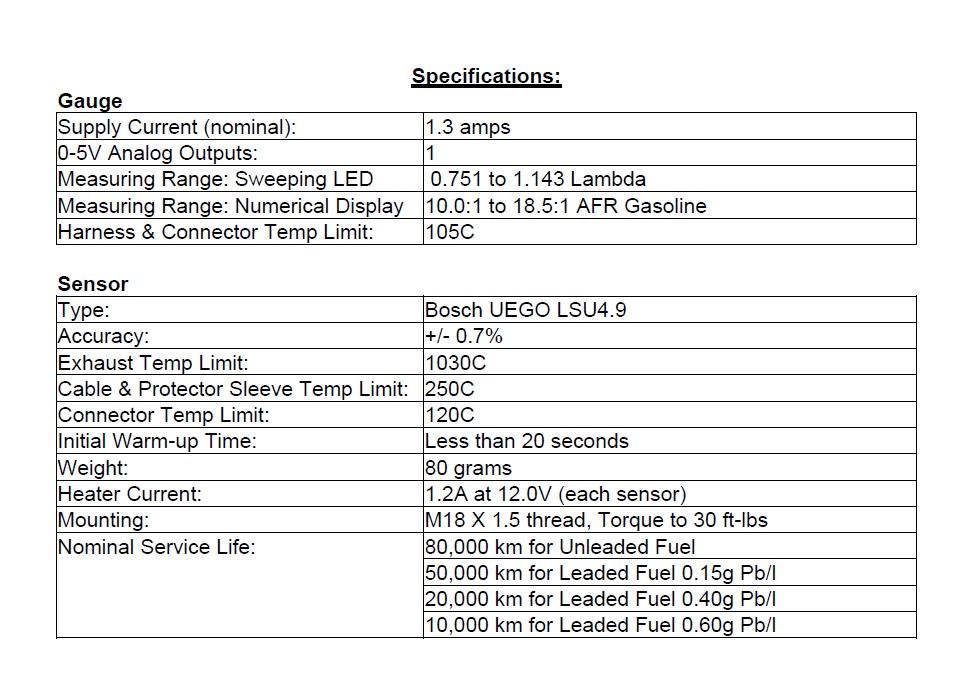
Aem air fuel ratio gauge wiring diagram wiring diagram is a simplified enjoyable pictorial representation of an electrical circuitit shows the components of the circuit as simplified shapes and the power and signal contacts between the devices. Each part ought to be placed and connected with other parts in particular manner.
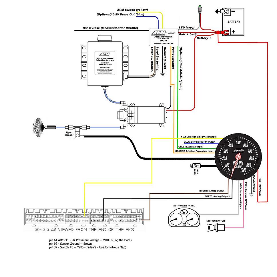
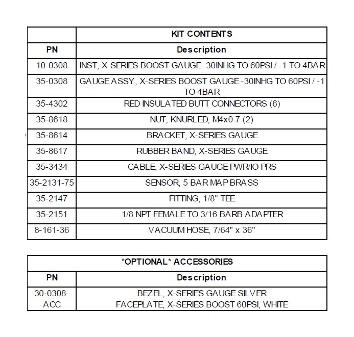
4955 Aem Boost Gauge Wiring Diagram Wiring Resources
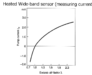
Aem uego wiring diagram. An easy way to do this is to disconnect the uego sensor from the uego gauge. When in this state the uego gauge will output 235 volts. Aem wideband wiring diagram aem uego sensor wiring diagram aem uego wideband wiring diagram aem uego wiring diagram every electrical structure is made up of various different pieces. 1 x bw uego gauge assembly. The bosch 49 lsu sensor used in the 30 4110 aem wideband uego afr controller gauge has a faster light off time and draws less current than the 42 lsu sensor used with aems 30 4100 wideband uego controller gauge which will be superseded to the 30 4110 gauge in august 2014. The uego sensor harness simply needs to be routed to the uego sensor whereas the powerio harness will.
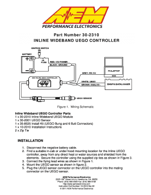
Interconnecting wire routes may be shown approximately where particular receptacles or fixtures must be upon a common circuit. The harnesses are connected to the gauge as shown below. Welcome to my blog here i will show you a little more what you are looking for aem 35 wiring diagram below there arefind best value and selection for your aem wideband o2 air fuel uego gauge only 35 tested works great search on ebay. Aem uego gauge 30 0300 x series architectural wiring diagrams be active the approximate locations and interconnections of receptacles lighting and steadfast electrical facilities in a building. Analog style wideband uego afr sensor controller gauge analog style boost pressure gauges 1 24bar 0 41ba analog style oil pressure gauges 0 69bar 0 10bar. Wiring schematic aem gauge type uego controller parts 1 x 35 5130bw uego gauge assembly 1 x 30 2001 uego sensor 1 x 35 8535 install kit o2 bung with 6 butt connectors 1 x 10 5130 installation instructions 1 x 35 3411 8 pin power harness 1 x 35 3400 6 pin sensor harness 1 x 35 8529s silver bezel.
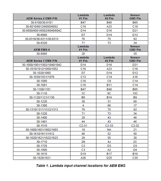
Aem 35 wiring diagram. When connecting to aems series1 ems make sure to verify that the o2 1 gain option is set so the voltage from the o2 1 volts parameter matches the voltage input at the ems from the o2 sensor. If not the arrangement will not function as it ought to be. Page 2 30 0300 x series uego gauge wiring installation diagram gauge connections the x series uego gauge is supplied with a powerio wiring harness a and a uego sensor harness b. Aem gauge type uego controller parts.
