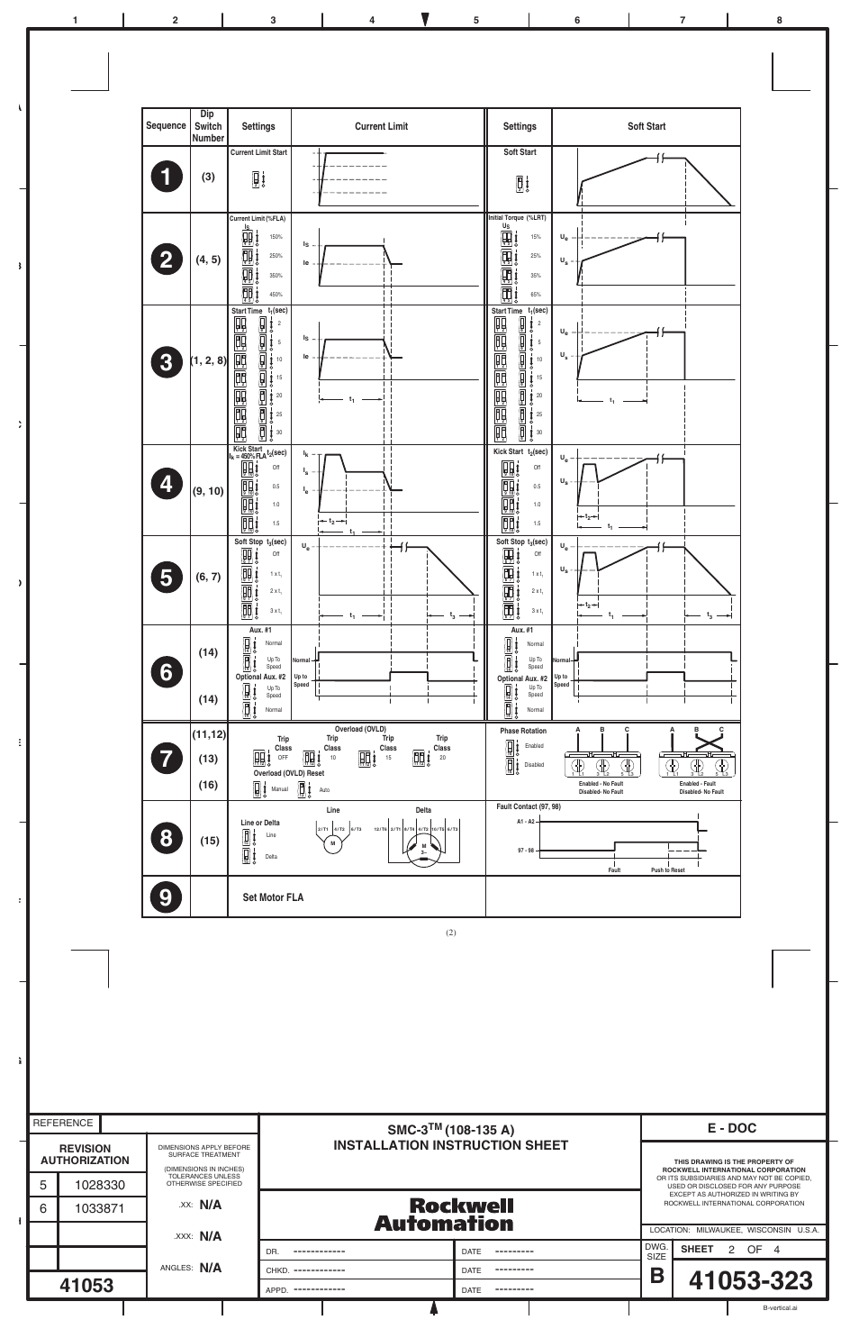
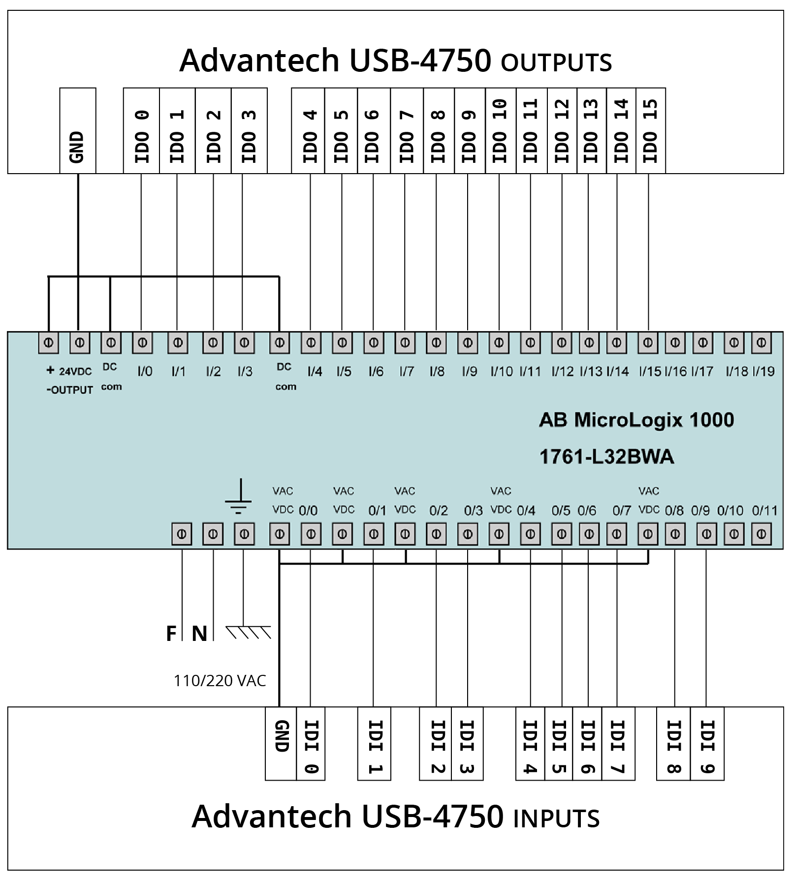
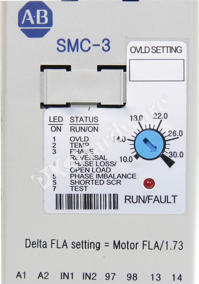
Ground a1 in1 in2a2 ovldfault aux 1 97 98 13 14 e1 tc sb1 e stop km e1 power connections sb3 start sb2 stop option km nema motor l35 l11 t12 t24 t36 l23 smc 3 power connections smc 3 control terminals e stop h4 h2 h1 h3 x1 x2 trans. They include overload protection integral bypass and motor and system diagnostics.
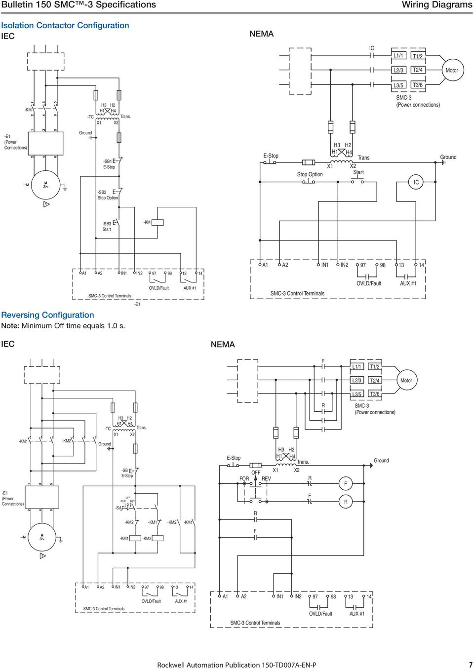
Smc 3 Specifications Pdf Free Download
Smc 3 soft starter wiring diagram. Mixed single and double wiring is available as. The standard connection of an electronic soft starter is 3 wire. Smc 3 low voltage soft starters. It features a built in overload relay and a built in scr bypass contactor on all three phases allowing a smaller footprint than other soft starters on the market. This video will help you to wire smc 3 soft starter from allen bradleypart i will be about 2 wire configuration. Repair pn 41391 801 repair pn 150 cs repair pn 150 fpp warning.
Smc 3 smc flex smc 50 kickstart user selectable voltage boost at startup to break away loads smc 3 smc flex smc 50 current limit user adjustable current limit start by maintaining a. An alternative connection is 6 wire or inside delta connection. If a mains or isolation contactor is used it is best controlled by the soft starter line relay. Bulletin 150 smart motor controllers smc 3 smart motor controller the smc 3 is a compact simple to use solid state motor controller designed to operate 3 phase motors. The smc 3 has been designed for class a equipment. Bulletin 150 smart motor controllers smc 3 smart motor controller the smc 3 is a compact simple to use solid state motor controller designed to operate 3 phase motors.
Smc 3tm soft starter installazioni a tre cavi arrancador suave smc 3tm instalaciones 3ø partida suave smc 3tm instalações trifásicas 41053 368 01 dir 41053 368 version 04 printed in usa. Our smc 3 soft starters are available with a current range from 3480 a. Allen bradley motor starter wiring diagram wiring diagram. B is used for the internal wiring of each station regardless of valve and option types. Wiring wiring on the double single low no. Control mode description diagram available with soft start output voltage is ramped from user adjustable initial torque setting out to user selectable start time.
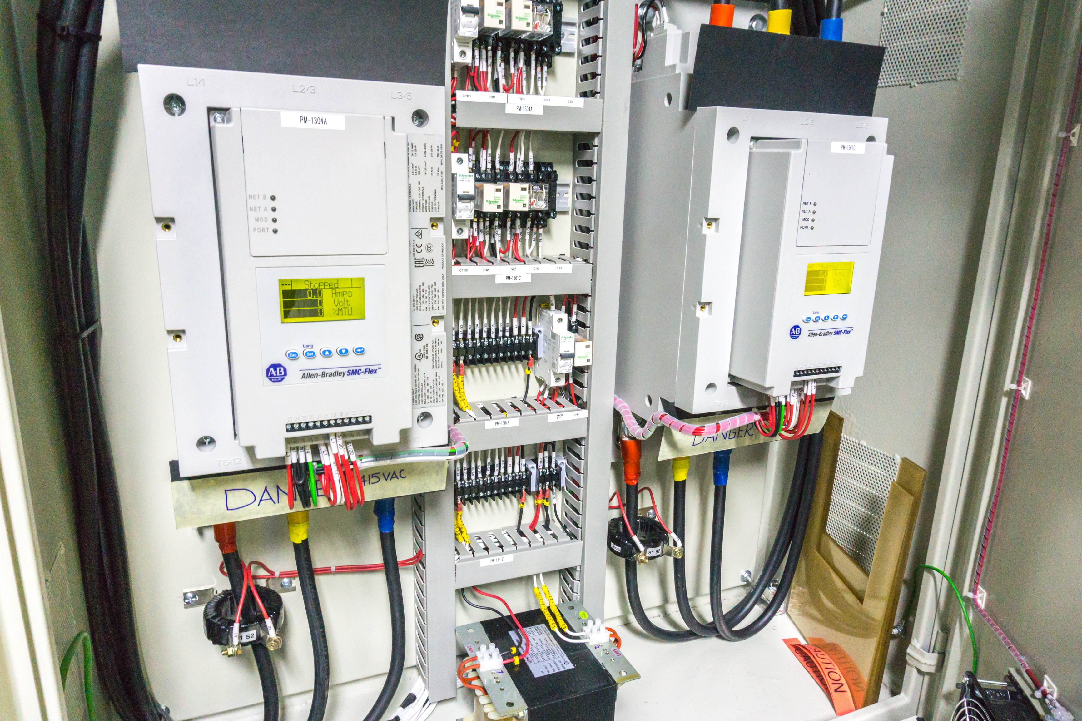
They feature compact true three phase control in a cost effective package. Use of the. Soft starter main circuit wiring the soft starter is installed between the mains and cable to the motor. It features a built in overload relay and a built in scr bypass contactor on all three phases allowing a smaller footprint than other soft starters on the market. Bulletin 150 smc 3 specifications wiring diagrams smc 3 control terminals h4 h2 h1 h3 x1 x2 trans. Allen bradley motor starter wiring diagram fresh fine allen bradley.
In part ii you will see 3 wire configuration with startstop push buttons. Allen bradley soft starter wiring diagram collection allen bradley smc 3 wiring diagram awesome famous allen bradley. Wiring diagram motor control system fresh allen bradley motor. Station wiring wiring side 1 for single wiring sq1000 017 to 023nm sq2000 025 to 035nm sq12000 tfj38gb 20 26 1 2 3 double wiring connected to sol.
