It shows the components of the circuit as streamlined shapes and also the power and also signal links between the gadgets. Connect one of the black or white leads to excitation negative and the other to channel negative.
Rtd Wiring Diagrams
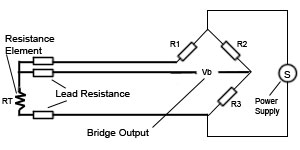
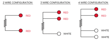
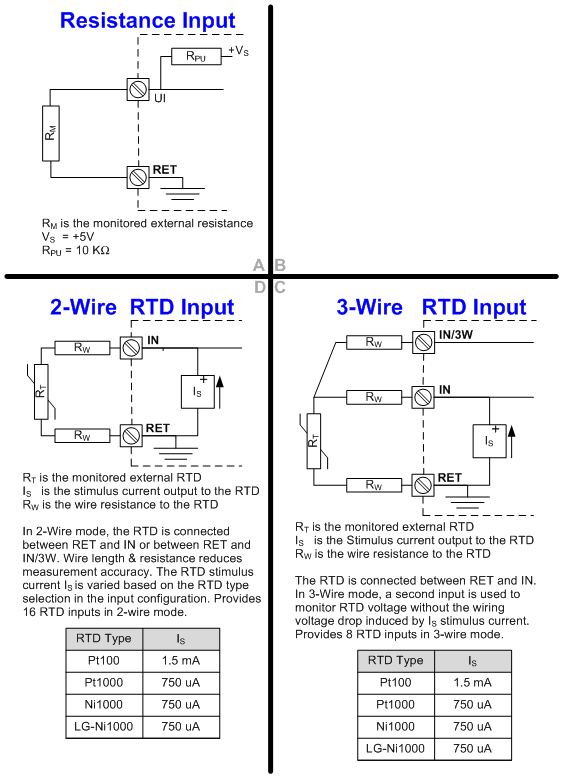
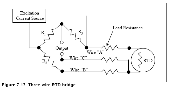
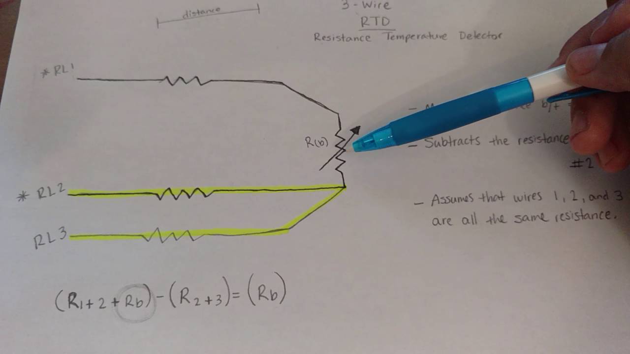
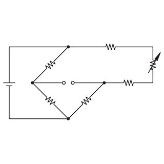
Rtd wiring diagram 3 wire. As long as the junctions are near the rtd as in a connection head errors are negligible. No current flows through it while the bridge is in balancesince l1 and l3 are in separate arms of the bridgeresistance is canceled. Rtd pt100 3 wire wiring diagram what is a wiring diagram. L1 and l3 carry the measuring current while l2 acts only as a potential lead. In this configuration two wires link the sensing element to the monitoring device on one side of the sensing element and one links it on its other side. Rtd theory page 3 2 wire construction is the least accurate of the 3 types since there is no way of eliminating the lead wire resistance from the sensor measurement.
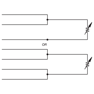
A wiring diagram is a simplified standard photographic representation of an electrical circuit. 3 wire rtd signal connection. It shows the components of the circuit as streamlined forms as well as the power and also signal links between the tools. Jumper the excitation positive to the channel positive on the daq device. 3 wire rtd wiring diagram in this circuit there are three leads coming from the rtd instead of two. A wiring diagram is a simplified conventional pictorial depiction of an electrical circuit.
Assortment of 3 wire rtd wiring diagram. Rtds are purchased with 2 3 or 4 lead wires per element. If necessary you can connect a 2 wire rtd to a 3 wire circuit or 4 wire circuit as shown. A wiring diagram is a straightforward visual representation of the physical connections and physical layout of your electrical system or circuit. What type of wiring system is currently in place if not new. It reveals the parts of the circuit as simplified forms and also the power and also signal links between the devices.
Difference between 2 wire rtd 3 wire rtd and 4 wire rtds rtds resistance temperature detectors are offered with 2 3 or 4 lead configuration. Collection of 3 wire rtd wiring diagram. 3 wire rtd connections. It shows how a electrical wires are interconnected which enable it to also show where fixtures and components may be coupled to the system. Connect the red lead to the excitation positive. A wiring diagram is a streamlined standard photographic depiction of an electrical circuit.
2 wire circuit wired to a 3 wire or a 4 wire circuit. Assortment of rtd pt100 3 wire wiring diagram. The 3 wire rtd configuration is the most commonly used rtd circuit design and can be seen in industrial process and monitoring applications. The best configuration for a specific application depends on a number of factors however the sensor configuration must match with transmitter otherwise leadwire resistance cancellation circuitry.
Gallery of Rtd Wiring Diagram 3 Wire


.jpg)


.jpg)