Replace a two wire pump. Use 25 mm2 awg 14 70 c copper conductors only and tighten all connections to 2 nm.

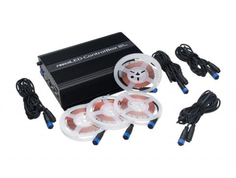
Medialight Flex 4 Meter 6500k Cri 95 Bias Lighting System
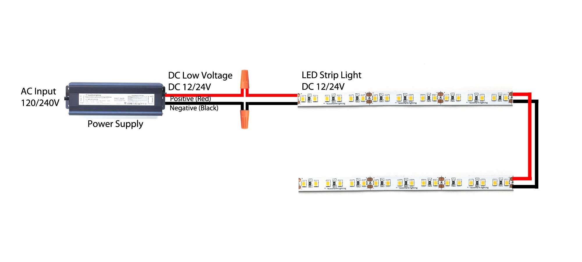
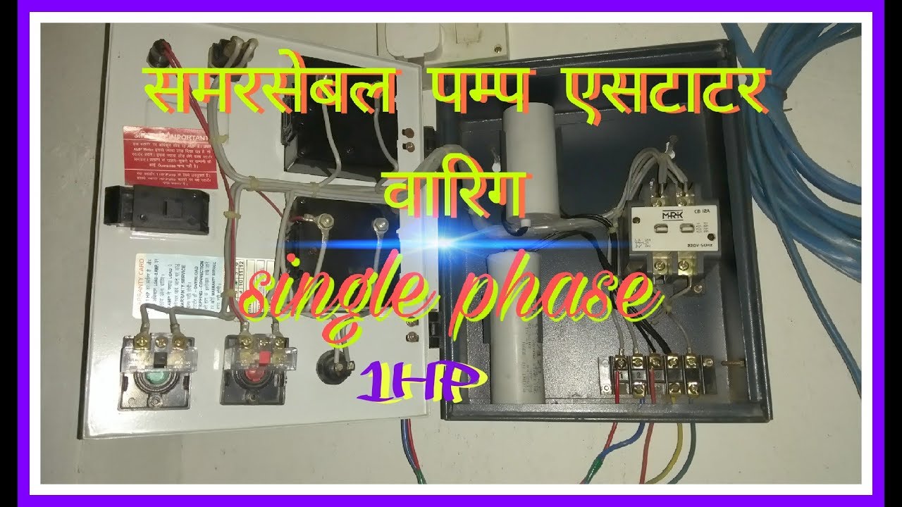
Cri control box wiring diagram. Single phase submersible pump control box wiring diagram 3 wire submersible pump wiring diagram in submersible pump control box we use a capacitor a resit able thermal overload and dpst switch double pole single throw. The wiring connection of submersible pump control box is very simple. Electronic control box cri. Provision of ammeter and voltmeter to check the voltage current in specific models only. Also it is a good idea to either use an in line fuse or an arp circuit breaker in line with the power supply to the control box. Make sure that the submersible pump the submersible motor and control box are designed for the same.
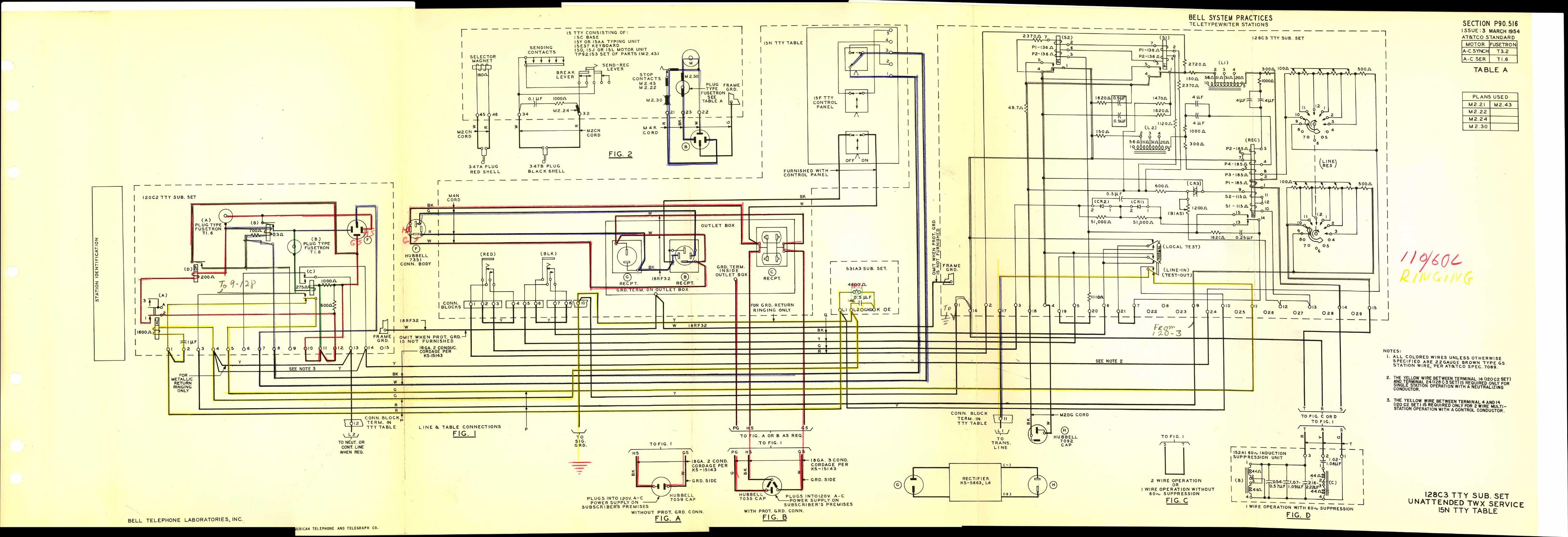
The diagrams for both the two and three wire pumps can be downloaded using adobe. 331 wiring connect the control box to the mains supply and the motor as shown in the wiring diagrams below. The green ground wire should also be terminated to the box and a ground coming from the panel. Single phase submersible motors are supplied with suitable control boxes which is mandatory. Schematic diagrams schematic diagrams show components in their electrical sequence without regard for physical location. Schematics are generally easier to read and understand than wiring diagrams.
Control box plus internal wiring diagram 230vac 50hz 185vac to 265vac 50hz 195vac to 275vac 50hz 5 to 60 degrees celsius trip time varies with severity of overload approximate 70 of normal shaft power runtime is automatically matched to water available for pumping auto reset after first two overloads with 15 minute delay then reset by. The arp yellow wire is connected to the violet wire that supplies power to the dometic control box eyebrow board. See also section 333 earthing on page 9. Wiring diagrams wiring diagrams show components mounted in their general location with connecting wires. The wiring diagram identifies the electrical terminals and lists their functions. The inbuilt micro controller gives complete protection to both single three phase pumps.
Here is the complete guide step by step. To replace the two wire pump. Control panels with ppr comprises of auto start provision and phase sequence protection i an option for float switch is provided in the control panel with ppr for the automatic operation of the pumpset based on water level. Control boxes are made of hi tech components and designed to perfection with various features to give ultimate protection to the prime movers such as submersible motors centrifugal pumps etc. After determining the voltage is zero disconnect the motor wires directly from the pressure switch box m1 and m2. Elcon control boxes are reliable control devices to protect your pumps against overloading unbalanced voltages dry run phase reversal phase failures.
4 this is the dometic control box see 3 for wiring. Schematic diagrams are used to troubleshoot and install control circuits. A wiring diagram is. The wires from the pressure switch connect to the electrical input terminals usually called l1 and l2 the wires heading to the wells pump motor connect to terminals with a start run. Inspect the control boxs wiring diagram located on the back of the lid.
Gallery of Cri Control Box Wiring Diagram