I set up my 450 heli apm 26 ver 321 with the radio on heli h1 and the apm to reciever using the cross channel futaba setup shown top picture of this post. Pitch and throttle curves are setup in radio have been flying it like this for a year or so.

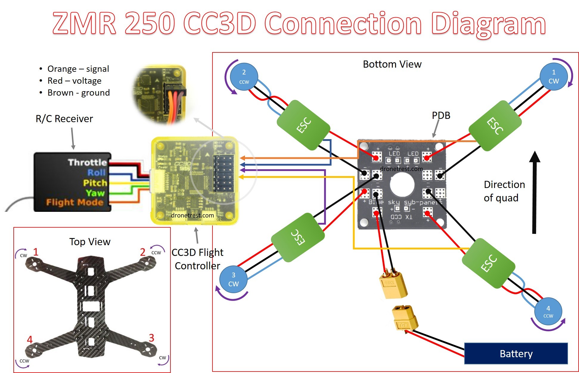
Ea 8021 Quadcopter Motor Wiring Diagram Schematic Wiring
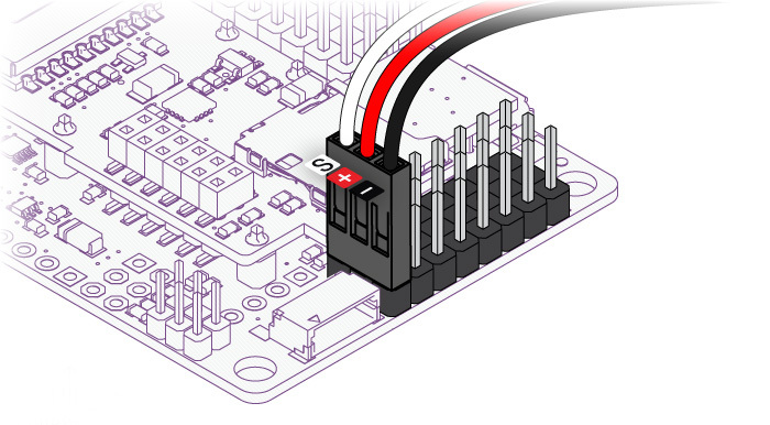
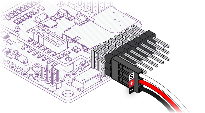
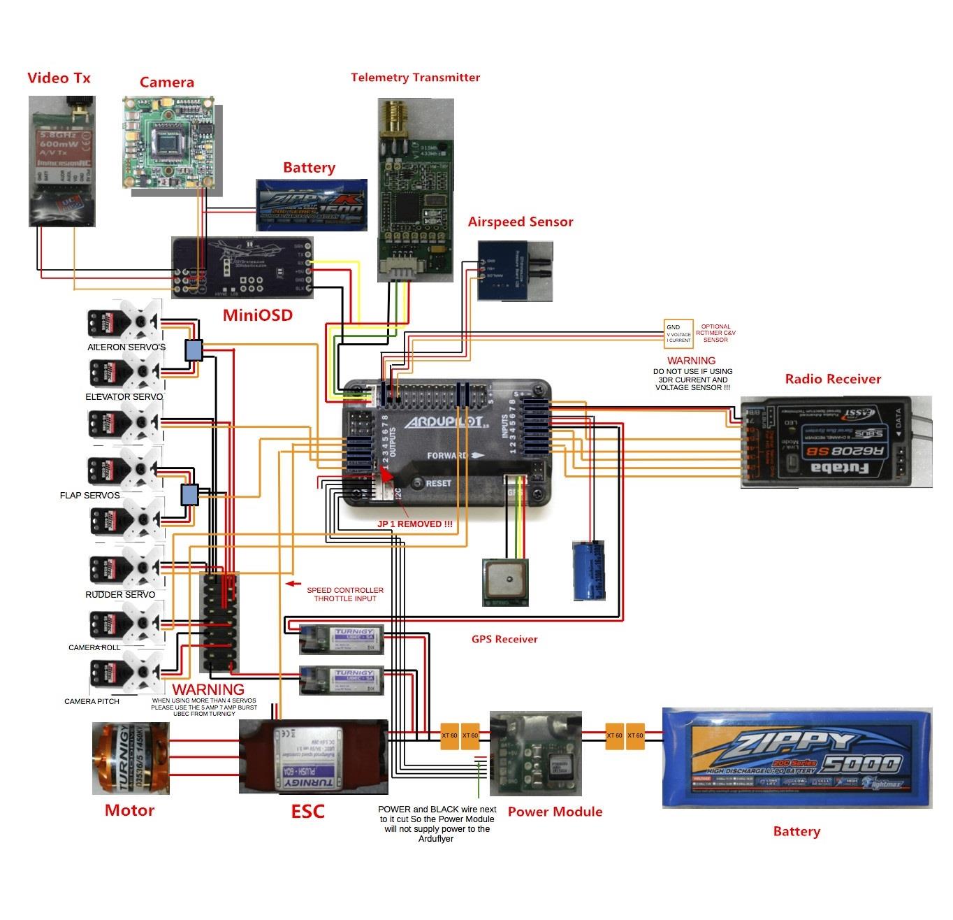
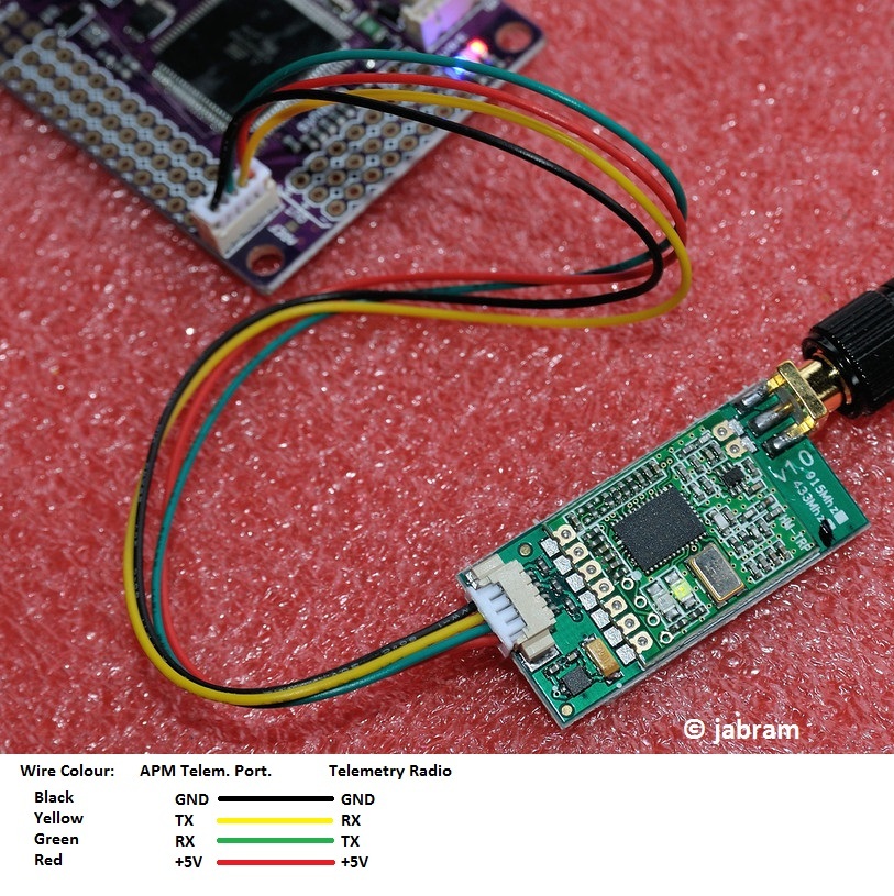
Apm 2 6 wiring diagram. Here is a diagram showing the pinout of the apm 26 telemetry port and in terms of the telemetry module here is a diagram showing the connectors between the apm and the telemetry module. All to be mounted on the mini talon. Apm wiring diagram wiring diagram is a simplified okay pictorial representation of an electrical circuitit shows the components of the circuit as simplified shapes and the capacity and signal associates amongst the devices. Connect the pdb multi wire cable to apm output signal pins with the m1 wire connecting to the signal pin labeled 1 m6 and signal pin 6 etc. I am using a flysky 9x radio and flysky 9 channel reciever that has the futaba channel order. We make extension cables for the 3dr telemetry radio.
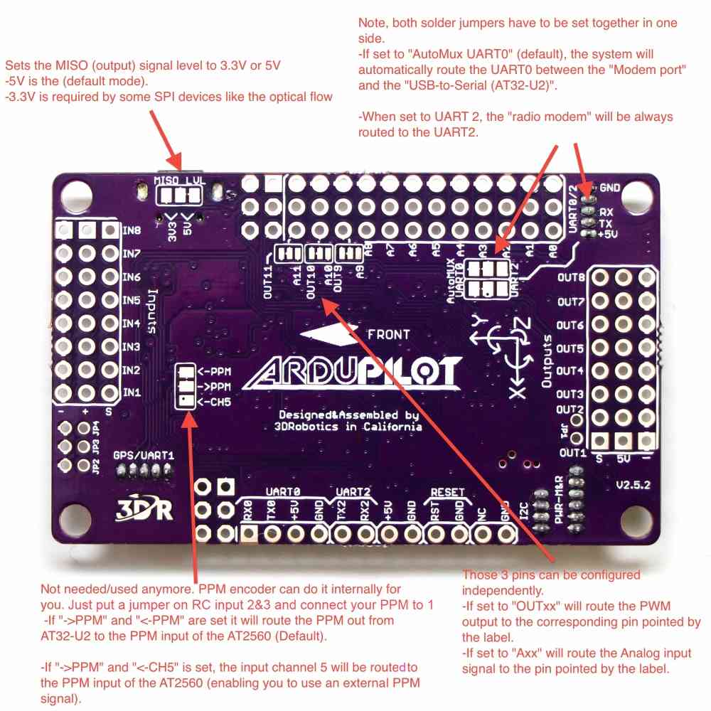
You still need an esc example wiring diagram for a bixler plane with apm. Reviewing wiring schematic and hook up wires for the ardupilot mega 26 to the ezuhf receiver. Reviewing wiring schematic and hook up wires for the ardupilot mega 26 to the ezuhf receiver. We connect the cables for the 3dr telemetry radio and minumosd. We make extension cables for the 3dr telemetry radio and minumosd. Apm wiring diagram detailed wiring diagrams fresh apm 2 6 wiring diagram quadcopter balnearios co apm pinout apm 2 6 wiring apm 2 5 wiring diagram could someone please direct me to a wiring diagram specific to each pin out not block diagram to the following.
To wire a power module connect the red and black two wire cable on the power module to the pdb red and black two wire. The main thing to take note of is that the rx port from apm connects to tx port of telemetry and tx on apm goes to rx on telemetry. Connect the power module to the apm pm port using a 6 position cable. All is mounted on the skywalker. Connections between rc receiver and ardupilot mega v2 board this can be dune by cutting the red wire on all but one of the escs or by using a specialjan 20 at tim dickinson the op has the apm which is a clone and its different from apm pin layout. A wiring diagram usually gives opinion about the relative aim and conformity of devices and terminals on the devices to incite in building or servicing the device.
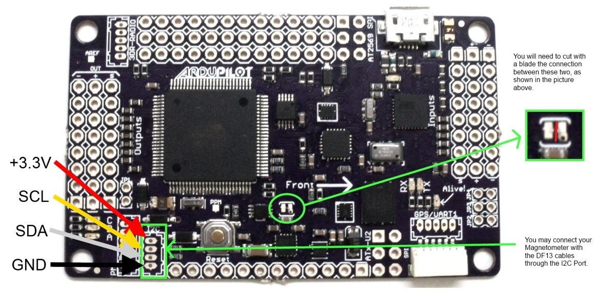
Apm 26 wiring 02102018 02102018 4 comments on apm 26 wiring the apm has no on board compass and is optimized for vehicles where the compass apm is designed to be used with the 3dr gps ublox lea 6 with archivedapm2x wiring quickstart powering the apm2 connecting the.

