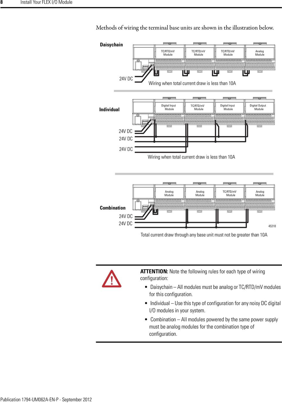
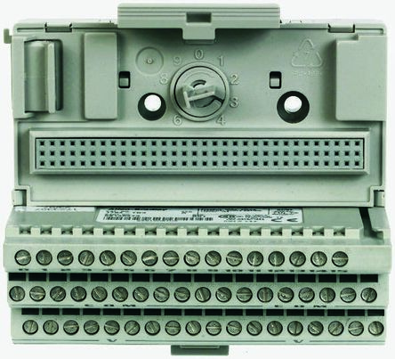
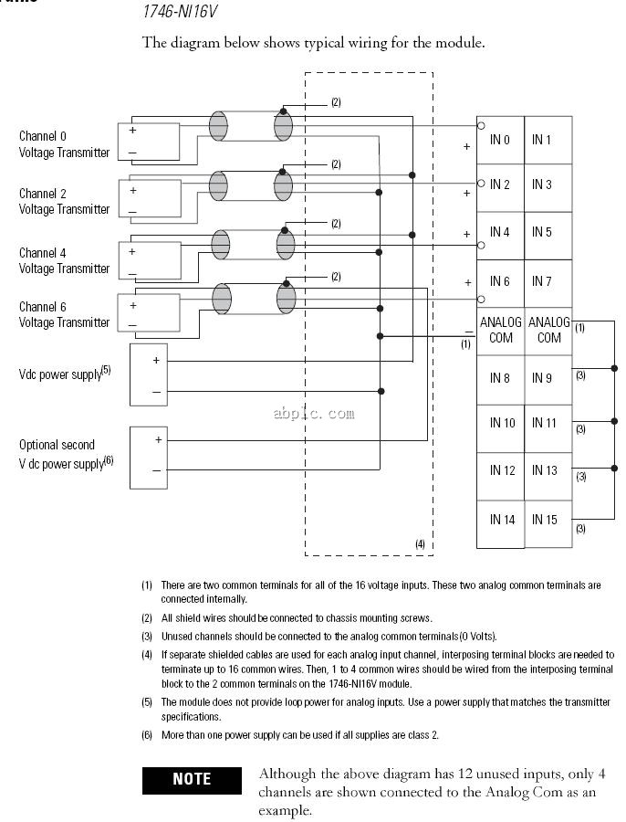
Wiring to a 1794 tbn or 1794 tbnf terminal base unit 33 24v dc common on this base unit to termi nal 16 on the next base unit. Warning if you connect or disconnect wiring while the field side power is on an.
1794 6 5 9 Remote I O Adapter Module User Manual Manualzz
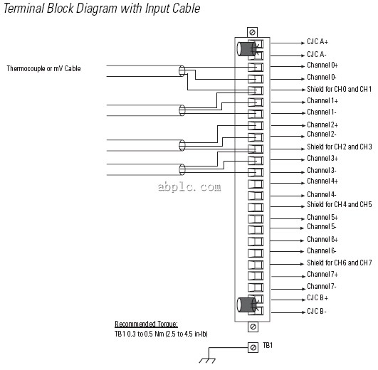
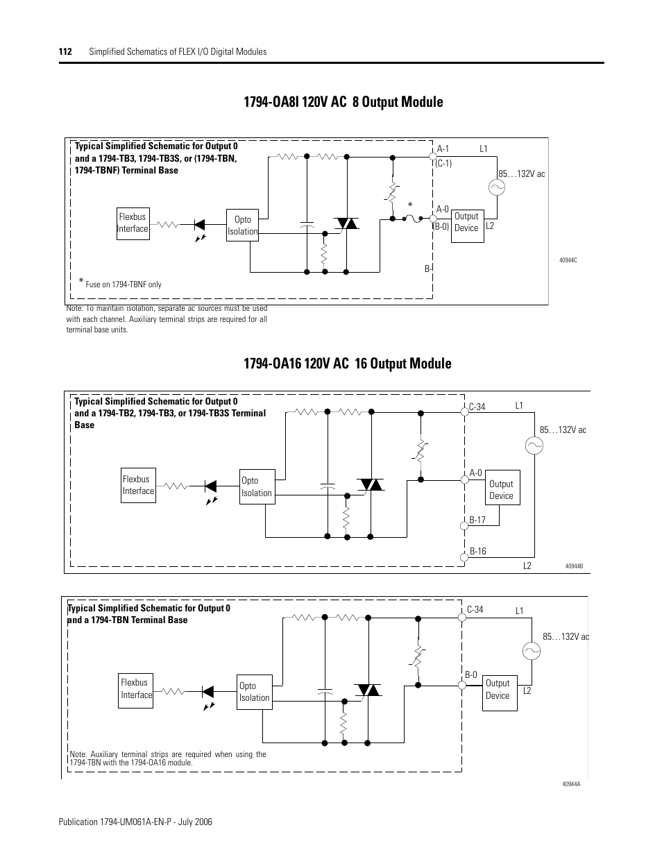
1794 tbnf wiring diagram. The table wiring connections for the 1794 oa8 and 1794 oa8k. A wiring diagram is a simplified conventional photographic representation of an electric circuit. 2 rockwell automation xxxx flex io high density analog modules user manual connect wiring to the ie8 the associated terminal on row b. Wiring diagrams help technicians to see the way the controls are wired to the system. Output output terminal2 2 auxiliary terminal blocks are required to connect the associated l2 common for each channel. 14 fuses eight 5x20 mm 1794 tbnf tbnfk only 15 terminal strip cover 1794 tbn tbnk tbnf tbnfk only.
Table 1 wiring connections for 1794 im16 and 1794 om16 1794 im16 1794 om16 1794 tbn 1794 tbn 1794 tbnf input input terminal1 1 auxiliary terminal blocks are required to distribute 240v ac power l1 to each device. Literally a circuit is the course that enables electricity to circulation. It reveals the parts of the circuit as streamlined forms and the power and signal connections in between the gadgets. Weve got allen bradley 1794 tbnf terminal base fused 16 point 22 12awg 10a 250v acdc at wholesale prices at rexel usa register now. Collection of 1794 tbnf wiring diagram youll be able to download free of charge. Flex io helps eliminate multiple long wiring runs reduces terminations per.
Variety of 1794 tbnf wiring diagram. Connect individual output wiring to even numbered terminals on the 1633 row b as indicated in the table below. Catalog numbers 1794 oa8 1794 oa8k 1794 oa8i 1794 oa16 table of contents topic page. The examples and diagrams in this manual are included solely for illustrative purposes. Wiring to a tbn or tbnf terminal base unit. The objective is the exact same.
The examples and diagrams in this manual are included solely for illustrative purposes. Connect the associated v ac common l2 lead of the output device to the corresponding odd. 1794 tbnf wiring diagram a novice s overview to circuit diagrams a first appearance at a circuit layout may be complex however if you could read a metro map you can check out schematics. Table 21 wiring connections for 1794 tb3 tb3t tb3s tb3ts tbn and tbnf terminal base units when using the 1794 if4i or 1794 of4i isolated analog module channel signal type label markings. For 1794 tbn or 1794 tbnf. Getting from point a to point b.
For 1794 tb2 1794 tb3 or 1794 tb3s. Please download these 1794 tbnf wiring diagram by using the download button or right select selected image then use save image menu. Because of the. Industrial automation wiring and grounding guidelines publication 1770 41 for more installation requirements.
