Use shielded communication cable belden 8761 and keep length as short as possible. 1746 nio4va series a rev a.
Gsm Input Module Gsm Input Module Suppliers And
1746 nio4v wiring diagram. Ab allen bradley battery configuration datasheet dimension firmware manual pdf price repair rockwell specification troubleshoot user. Slc 500 1746 ni4 io systems pdf manual download. Please refer to the manual for more information about the 1746 nio4v such as the wiring diagrams data sheets firmware information and migration or obsolescence details. Slc 500 4 channel analog io modules catalog numbers 1746 ni4 1746 nio4i 1746 nio4v 1746 no4i and 1746 no4v user manual. In both modules the current or voltage ranges are independently configurable for each channel. 1746 ni4 35 ma 85 ma 1746 nio4i 55 ma 145 ma 1746 nio4v 55 ma 115 ma 1746 no4i 55 ma 195 ma1 2 1 the 24v dc user power connection on a fixed slc 500 can power an no4i or no4v analog module.
Revision part also known as. Customers are encouraged to migrate to our compact 5000 io modules used with the logix control platform. View and download allen bradley slc 500 1746 ni4 installation instruction online. However the regulation of the 24v dc user connection on a modular slc 500 power supply catalog number 1746 p1 p2 and p4 is outside of the. Voltage out ab 1746 n 1746 ni 1746 nio 1746 nio4 download our 1746 nio4v wiring diagram download the latest 1746 nio4v pdf manual for technical information. 0 to 5v cd 1 to 5v cd.
Rockwell automation announces that as of august 31 2018 additional bulletin 1746 io modules will be discontinued and no longer available for sale. Our bulletin 1746 slc io modules are part of our slc 500 control platform. These modules also provide new advanced. Connect only one end of the cable shield to earth ground. 0 to 10v dc 1 lsb includes. I last letter current output current input for 1746 ni16i v voltage output voltage input for 1746 ni16v 1746 fio4i and fio4v ni4 ni8 ni16i and ni16v nio4i and nio4v 6 2 2481 s t u p n i f o r e b m u n voltage input ranges select a current or voltage signal for each channel.
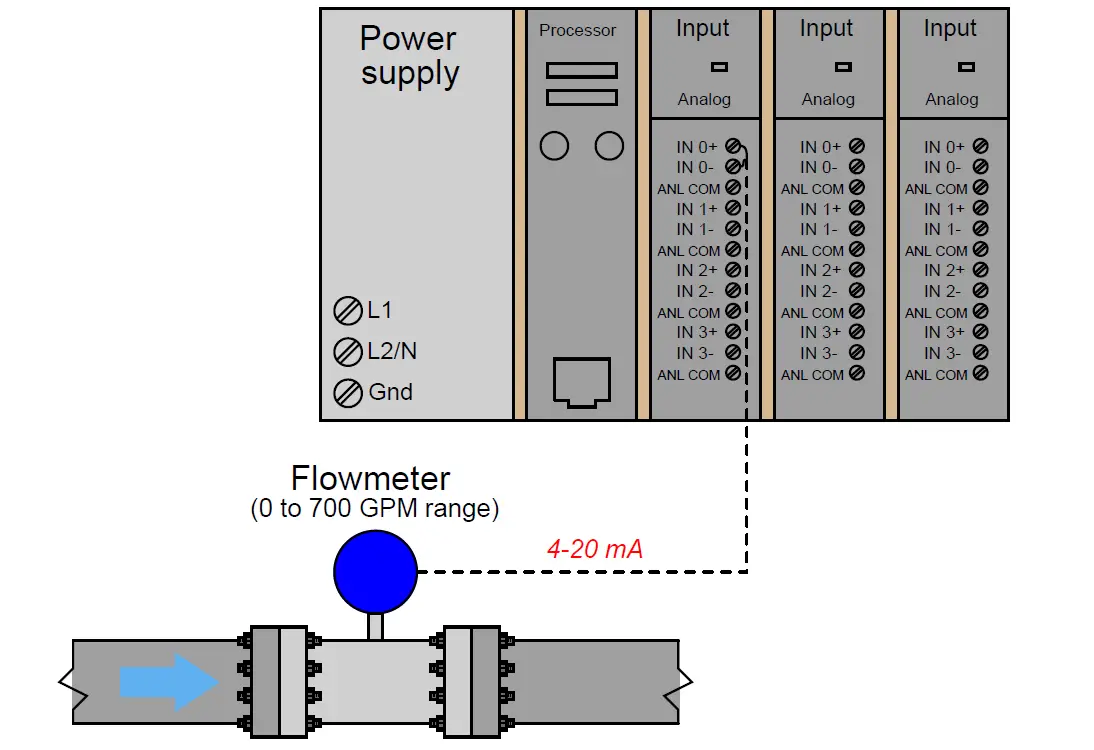
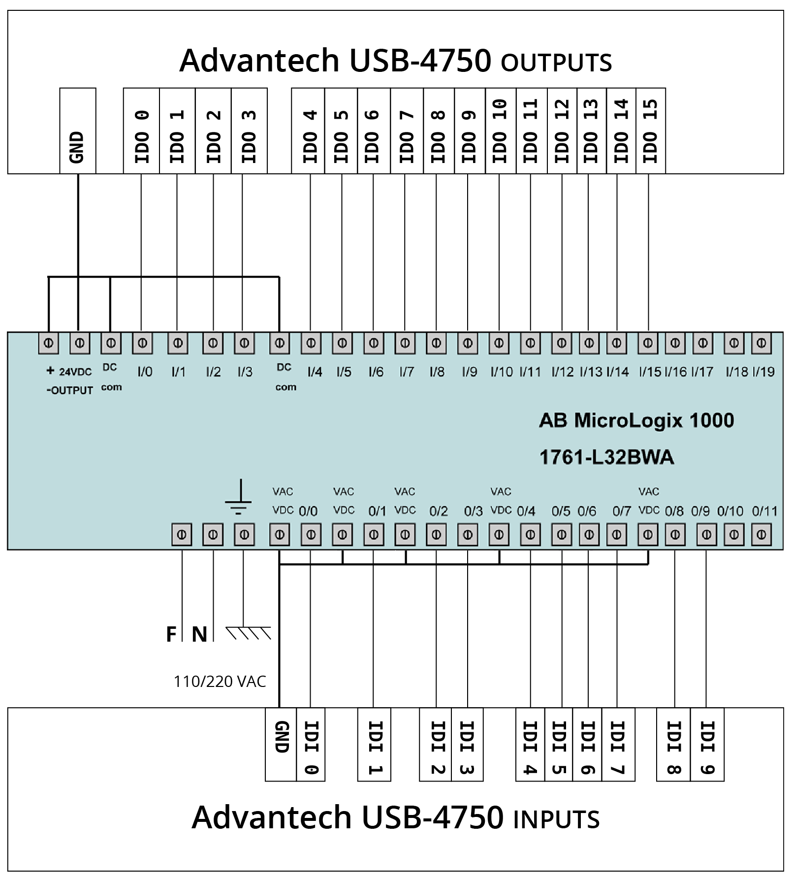
Connect the shield drain wires for channels 0 to 3 to the top shield terminal. The following diagram shows typical wiring for the 1746 ni8 module. 1746 ib16 1746 ic16 1746 ig16 1746 ih16 1746 im4 1746 im8. 1 publication 1746 um026a en p september 2003 chapter 1 overview what the module does the 1746 no8i provides eight channels of current outputs while the 1746 no8v provides eight channels of voltage outputs. Slc 500 1746 nio4i slc 500 1746 nio4v slc 500 1746 no4i slc 500 1746 no4v slc 500 1746 fio4i slc 500 1746 fio4v. Wiring diagrams 17 apply the octal filter label 6 apply the octal door label 6 removable terminal blocks 6 recovery from blown fuseprocessor faultprocessor shutdown 13 replacement fuse recommendations 13 replace fuses 14.
Common related search terms.


